11
returns to admissible levels, the tool will operate as
normal.
Soft start feature
• Soft start because of suppressed starting shock.
Speed adjusting dial
For model RP2300FC, RP2301FC only (Fig. 5)
The tool speed can be changed by turning the speed
adjusting dial to a given number setting from 1 to 6.
Higher speed is obtained when the dial is turned in the
direction of number 6. And lower speed is obtained when
it is turned in the direction of number 1.
This allows the ideal speed to be selected for optimum
material processing, i.e. the speed can be correctly
adjusted to suit the material and bit diameter.
Refer to the table for the relationship between the number
settings on the dial and the approximate tool speed.
CAUTION:
• If the tool is operated continuously at low speeds for a
long time, the motor will get overloaded, resulting in
tool malfunction.
• The speed adjusting dial can be turned only as far as 6
and back to 1. Do not force it past 6 or 1, or the speed
adjusting function may no longer work.
Lighting up the lamps
For model RP1800F, RP1801F, RP2300FC, RP2301FC
only (Fig. 6)
CAUTION:
• Do not look in the light or see the source of light
directly.
Pull the switch trigger to turn on the light. The lamp keeps
on lighting while the switch trigger is being pulled.
The lamp turns off 10 - 15 seconds after releasing the
trigger.
NOTE:
• Use a dry cloth to wipe the dirt off the lens of lamp.Be
careful not to scratch the lens of lamp, or it may lower
the illumination.
ASSEMBLY
CAUTION:
• Always be sure that the tool is switched off and
unplugged before carrying out any work on the tool.
Installing or removing the bit (Fig. 7)
CAUTION:
• Install the bit securely. Always use only the wrench
provided with the tool. A loose or overtightened bit can
be dangerous.
• Use always a collet which is suitable for the shank
diameter of the bit.
• Do not tighten the collet nut without inserting a bit or
install small shank bits without using a collet sleeve.
Either can lead to breakage of the collet cone.
• Use only router bits of which the maximum speed, as
indicated on the bit, does exceed the maximum speed
of the router.
Insert the bit all the way into the collet cone. Press the
shaft lock to keep the shaft stationary and use the wrench
to tighten the collet nut securely. When using router bits
with smaller shank diameter, first insert the appropriate
collet sleeve into the collet cone, then install the bit as
described above.
To remove the bit, follow the installation procedure in
reverse.
OPERATION
CAUTION:
• Before operation, always make sure that the tool body
automatically rises to the upper limit and the bit does
not protrude from the tool base when the lock lever is
loosened.
• Before operation, always make sure that the chip
deflector is installed properly.
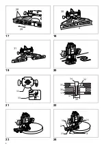
(Fig. 8)
Always use both grips and firmly hold the tool by both
grips during operations.
Set the tool base on the workpiece to be cut without the
bit making any contact. Then turn the tool on and wait until
the bit attains full speed. Lower the tool body and move
the tool forward over the workpiece surface, keeping the
tool base flush and advancing smoothly until the cutting is
complete.
When doing edge cutting, the workpiece surface should
be on the left side of the bit in the feed direction.
(Fig. 9)
NOTE:
• Moving the tool forward too fast may cause a poor
quality of cut, or damage to the bit or motor. Moving the
tool forward too slowly may burn and mar the cut. The
proper feed rate will depend on the bit size, the kind of
workpiece and depth of cut. Before beginning the cut
on the actual workpiece, it is advisable to make a
sample cut on a piece of scrap lumber. This will show
exactly how the cut will look as well as enable you to
check dimensions.
• When using the straight guide or the trimmer guide, be
sure to install it on the right side in the feed direction.
This will help to keep it flush with the side of the
workpiece.
(Fig. 10)
Straight guide (Fig. 11)
The straight guide is effectively used for straight cuts
when chamfering or grooving.
Install the straight guide on the guide holder with the
clamping screw (B). Insert the guide holder into the holes
in the tool base and tighten the clamping screw (A).
To adjust the distance between the bit and the straight
guide, loosen the clamping screw (B) and turn the fine
adjusting screw (1.5 mm per turn). At the desired
distance, tighten the clamping screw (B) to secure the
straight guide in place.
(Fig. 12)
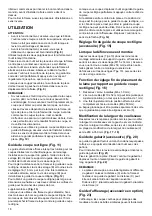
Number
min
-1
1
9,000
2
11,000
3
14,000
4
17,000
5
20,000
6
22,000
Содержание RP1800F
Страница 2: ...2 1 2 3 4 5 6 7 8 1 2 3 4 5 6 7 8 9 8 10 6 11 12 13 14 15 16 ...
Страница 3: ...3 9 10 11 12 13 14 15 16 17 18 19 20 20 18 20 18 17 21 21 22 23 24 25 26 21 55 mm 55 mm 27 22 ...
Страница 4: ...4 17 18 19 20 21 22 23 24 28 29 30 d 31 32 33 34 35 36 17 37 38 32 39 22 23 40 41 24 ...
Страница 5: ...5 25 26 27 28 29 30 31 32 17 34 42 44 43 45 46 45 46 47 46 48 49 ...
Страница 6: ...6 33 34 35 36 37 38 39 40 50 51 52 53 51 R ...
Страница 7: ...7 41 42 43 44 45 46 47 48 ...
Страница 8: ...8 49 50 51 ...


