9
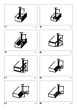
Drill point double flush trimming bit (Fig. 21)
mm
009807
Corner rounding bit (Fig. 22)
mm
009808
Chamfering bit (Fig. 23)
mm
009809
Cove beading bit (Fig. 24)
mm
009810
Ball bearing flush trimming bit (Fig. 25)
mm
009811
Ball bearing corner rounding bit (Fig. 26)
mm
009812
Ball bearing chamfering bit (Fig. 27)
mm
009813
Ball bearing beading bit (Fig. 28)
mm
009814
Ball bearing cove beading bit (Fig. 29)
mm
009815
Ball bearing roman ogee bit (Fig. 30)
mm
009816
NOTE:
• Some items in the list may be included in the tool
package as standard accessories. They may differ
from country to country.
Noise
ENG905-1
The typical A-weighted noise level determined according
to EN60745:
Sound pressure level (L
pA
): 89 dB (A)
Sound power level (L
WA
): 100 dB (A)
Uncertainty (K): 3 dB (A)
Wear ear protection.
Vibration
ENG900-1
The vibration total value (tri-axial vector sum) determined
according to EN60745:
Work mode: cuttig grooves in MDF
Vibration emission (a
h
): 4.0 m/s
2
Uncertainty (K): 1.5 m/s
2
ENG901-1
• The declared vibration emission value has been
measured in accordance with the standard test method
and may be used for comparing one tool with another.
• The declared vibration emission value may also be
used in a preliminary assessment of exposure.
WARNING:
• The vibration emission during actual use of the power
tool can differ from the declared emission value
depending on the ways in which the tool is used.
• Be sure to identify safety measures to protect the
operator that are based on an estimation of exposure in
the actual conditions of use (taking account of all parts
of the operating cycle such as the times when the tool
is switched off and when it is running idle in addition to
the trigger time).
D
A
L 1
L 2
L 3
L 4
8 8 80 55 20 25
6 6 70 40 12 14
D
A 1
A 2
L 1
L 2
L 3
R
6 25 9 48 13 5 8
6 20 8 45 10 4 4
D
A
L 1
L 2
L 3
6 23 46 11 6 30°
6 20 50 13 5 45°
6 20 49 14 2 60°
D A L
1
L
2 R
6 20 43 8 4
6 25 48 13 8
D A L
1
L
2
6
10 50 20
1/4”
D
A 1
A 2
L 1
L 2
L 3
R
6 15 8 37 7 3.5 3
6
21 8 40 10 3.5 6
1/4”
D
A 1
A 2
L 1
L 2
6
26 8 42 12 45°
1/4”
6
20
8
41
11
60°
D
A 1
A 2
A 3
L 1
L 2
L 3
R
6 20 12 8 40 10 5.5 4
6 26 12 8 42 12 4.5 7
D A
1 A
2 A
3 A
4 L
1 L
2 L
3 R
6 20 18 12 8 40 10 5.5 3
6 26 22 12 8 42 12 5 5
D
A 1
A 2
L 1
L 2
L 3
R1
R2
6 20 8 40 10 4.5 2.5 4.5
6 26 8 42 12 4.5 3 6


