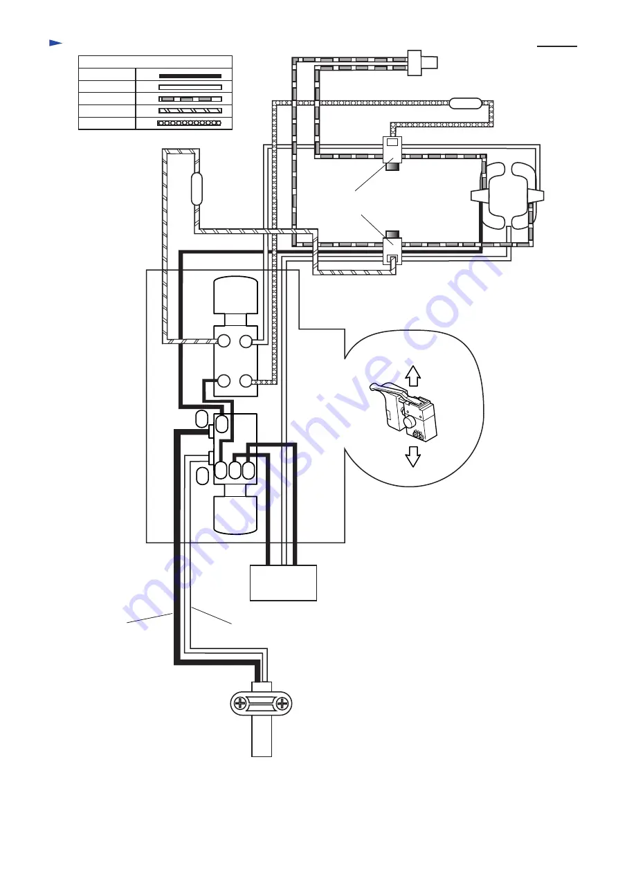
Makita Maktec MT811 Скачать руководство пользователя страница 4

C

ircuit diagram

P 4 / 7

Color index of lead wires

Black
White

Red

Orange
Purple

A

B

Black
or brown

White 
or blue

1a 1b 2b

2a

1

2

4

6

3

5

Noise 
    suppressor

Switch
A side

Switch
B side

Brush
holders

Field

P 5 / 

Insulated 
terminal

Choke coil

Choke coil

Switch

Содержание Maktec MT811

Страница 1: ...ATION CONCEPT AND MAIN APPLICATIONS Specification Standard equipment Optional accessories Note The standard equipment for the tool shown may differ from country to country P 1 7 Chuck ability mm Keyless chuck Reverse switch No load speed min 1 rpm Blows per min min 1 bpm Drilling capacity mm Steel Concrete Chuck key S13 1 pc Side grip 1 pc Wood Protection from electric shock Net weight Kg lbs Cord...

Страница 2: ...ing No 1R298 hex socket with drill chuck and turn the hex socket with No 1R223 Torque wrench anti clockwise So drill chuck can be disassembled from spindle See Fig 1 3 Assembling drill chuck 4 Disassembling and assembling cam Disassembling Hold inner housing with vise Insert the screwdriver into the space between cam and inner housing Disassemble cam with the screwdriver as illustrated in Fig 2 Fi...

Страница 3: ...s 2 Assemble helical gear 39 to spindle by pressing 1R028 Bearing setting pipe on the helical gear with arbor press 3 Fix helical gear 39 with retaining ring S12 and put steel ball 3 5 and pin 4 into the hole of spindle Fig 4 Fig 5 Retaining ring S12 Steel ball 3 5 Pin 4 Spindle Spindle Note Be careful not to lose pin 4 steel ball 3 5 and retaining ring S12 when removing them No 1R284 Round bar fo...

Страница 4: ...olor index of lead wires Black White Red Orange Purple A B Black or brown White or blue 1a 1b 2b 2a 1 2 4 6 3 5 Noise suppressor Switch A side Switch B side Brush holders Field Insulated terminal Choke coil Choke coil Switch ...

Страница 5: ...llustrated below Boss A 6 4 Pass field lead wire red between rib B and rib C as illustrated below Be careful not to pinch the lead wires connected with switch terminal 4 and 6 with boss A Pass field lead wire black between rib D and rib E Pass field lead wire white between rib A and rib B Polyethylene tube Pass field lead wire red between rib E and rib F Wiring diagram of lower portion of switch N...

Страница 6: ... Inflect the receptacles as illustrated in Fig A The receptacle of lower brush holder side has to be so inflected that it does not cross the line of Choke coil orange Choke coil purple Noise suppressor s lead wire white Pass noise suppressor s lead wire white and choke coil lead wire orange between rib E and rib F Lead wire purple Pass noise suppressor s lead wire white and choke coil lead wire or...

Страница 7: ... 4 and 6 with boss A Brush holder Brush holder Receptacle Switch Fig B Upper Lower Receptacle Inflect the receptacles as illustrated in Fig B The receptacle of lower brush holder has to be so inflected that it does not cross the line of Pass noise suppressor s lead wire white and lead wire orange between rib E and rib F Lead wire purple Switch Wiring diagram of lower portion of switch Noise suppre...

Отзывы: