


[3] DISASSEMBLY/ASSEMBLY
[3]-5. Hammering mechanism
(1) Remove Hammer section by steps drawn in
Fig. 2 to Fig. 7
.
(2)
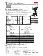
Press down Hammer to the full with 1R045 and then reverse the handle to align the openings in Hammer
with the top of cam groove on Spindle.
(3) Remove two Steel balls 5.6 from Spindle using Tweezers or 1R288. (
Fig. 23
)
(4) When Hammer is separated from Spindle, the setting posture is turned upside down from shown in
Fig. 23 to
Fig. 24
to prevent Steel balls 3.5 from being dropped.
There are 24pcs. of Steel balls 3.5 in the groove of Hammer.
(As drawn in
Fig. 25
, the groove is designed to have a space equivalent to one Steel ball 3.5.)
P
7
/ 1
1
R
epair
Fig. 23
Fig. 24
Fig. 25
Right
Wrong
Hammer
Hammer
Hammer
Spindle end
Spindle end
Spindle end
Spindle top
1R045
Top of
Cam groove
on Spindle
Opening for
Steel ball
insertion
space equivalent to
one Steel ball 3.5
Steel ball 5.6
(2pcs.)
DISASSEMBLING
Reverse the disassembling step.
ASSEMBLING
Steel ball 3.5
(24pcs.)
Inside view of Hammer