P 12 /20
R
epair
[3] DISASSEMBLY/ASSEMBLY
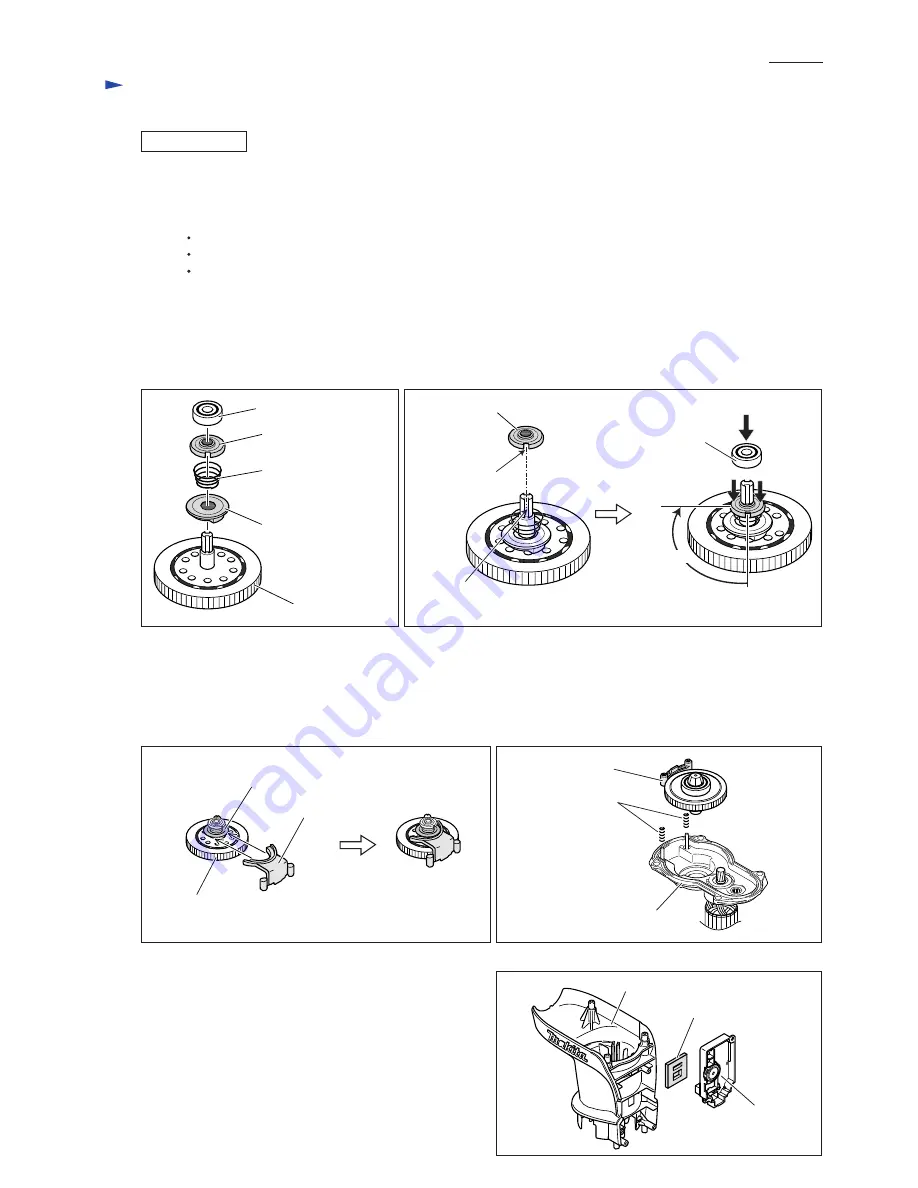
Fig. 34
Fig. 35
Fig. 36
Fig. 37
Fig. 37
Do the reverse of the disassembling steps. Remember the following notes.
Note 1. When Assembling Torque Limiter Assembly
Note 2. When Installing Torque Limiter Assembly on Gear Housing Complete
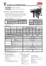
Note. 3. Do not forget to put Sponge sheet between
Controller and Motor housing complete. (Fig. 38)
ASSEMBLING
Cup washer 8
Ball bearing
608DDW
Driving flange
Torque limiter
Conical compression
spring 19-27
Groove on
Straight bevel gear 7
notch
largest gear of
Torque limiter
Change plate
Driving flange
1) Conical compression spring 19-27 and Driving flange are not reversible when assembled to Torque limiter.
As illustrated in Fig. 34, be sure to assemble so that;
Driving flange: the flanged end faces the Conical compression spring side.
Conical compression spring: the smaller diameter end faces the Driving flange side.
Cup washer 8: the side with a raised center faces the Ball bearing 608DDW side.
2) When assembling Cup washer 8 to Straight bevel gear 7 of Torque limiter;
first insert Cup washer 8 through Straight bevel gear 7 with the notch in the Cup washer aligned with the groove
on the Straight bevel gear. Then while pressing down Cup washer 8, turn the Cup washer 90 degrees.
Now Cup washer 8 is pre-fastened to Straight bevel gear 8, then securely fastened by press-fitting Ball bearing
608DDW with arbor press. (Fig. 35)
Cup washer 8
Ball bearing 608DDW
90 degrees
1) Set Change plate between Driving flange and the largest gear of Torque limiter. (Fig. 36)
2) Do not forget to insert Compression springs through the pins on Gear housing complete. (Fig. 37)
3) The Change plate installation side should be placed on the Compression spring installation side
of Gear housing complete. (Fig. 37)
Gear housing complete
Compression
spring 5
Change plate
Controller
Motor housing complete
Sponge sheet


