12 ENGLISH
FUNCTIONAL
DESCRIPTION
CAUTION:
Always be sure that the tool is
switched off and unplugged before adjusting or
checking function on the tool.
CAUTION:
Return the switch trigger to the
"OFF" position in case of accidental unplugging,
blackout, or the power is cut unintentionally.
Otherwise the tool may start suddenly when the
power returns and it may result in personal injury.
Shaft lock
Press the shaft lock to prevent spindle rotation when
installing or removing accessories.
►
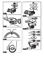
Fig.1:
1.
Shaft lock
NOTICE:
Never actuate the shaft lock when the
spindle is moving.
The tool may be damaged.
Switch handle mounting positions
CAUTION:
Always make sure that the switch
handle is locked in the desired position before
operation.
The switch handle can be rotated to either 90° left or
right to fit your work needs. First, unplug the tool. Press
the lock button and rotate the switch handle to left
or right fully. The switch handle will be locked in that
position.
GA7070, GA9070
►
Fig.2:
1.
Motor housing
2.
Lock button
3.
Handle
GA7071, GA9071
►
Fig.3:
1.
Motor housing
2.
Lock button
3.
Handle
Switch action
CAUTION:
Before plugging in the tool, always
check to see that the switch trigger actuates
properly and returns to the "OFF" position when
released.
There are three patterns of the switch action depending
on country.
GA7070, GA9070
►
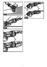
Fig.4:
1.
Switch trigger
2.
Lock lever
GA7071, GA9071
►
Fig.5:
1.
Switch trigger
2.
Lock lever
For tool with the lock-on switch
Country specific
CAUTION:
Switch can be locked in "ON" posi-
tion for ease of operator comfort during extended
use. Apply caution when locking tool in "ON"
position and maintain firm grasp on tool.
To start the tool, simply pull the switch trigger (in the B
direction). Release the switch trigger to stop.
For continuous operation, pull the switch trigger (in the
B direction) and then push in the lock lever (in the A
direction).
To stop the tool from the locked position, pull the switch
trigger fully (in the B direction), then release it.
For tool with the lock-off switch
Country specific
To prevent the switch trigger from accidentally pulled, a
lock lever is provided.
To start the tool, push in the lock lever (in the A direc
-
tion) and then pull the switch trigger (in the B direction).
Release the switch trigger to stop.
NOTICE:
Do not pull the switch trigger hard
without pressing in the lock lever.
This can cause
switch breakage.
For tool with the lock-on and lock-off
switch
Country specific
CAUTION:
Switch can be locked in "ON" posi-
tion for ease of operator comfort during extended
use. Apply caution when locking tool in "ON"
position and maintain firm grasp on tool.
To prevent the switch trigger from accidentally pulled, a
lock lever is provided.
To start the tool, push in the lock lever (in the A direc
-
tion) and then pull the switch trigger (in the B direction).
Release the switch trigger to stop.
For continuous operation, push in the lock lever (in the
A direction), pull the switch trigger (in the B direction)
and then pull the lock lever (in the C direction).
To stop the tool from the locked position, pull the switch
trigger fully (in the B direction), then release it.
NOTICE:
Do not pull the switch trigger hard
without pressing in the lock lever.
This can cause
switch breakage.
Indication lamp
►
Fig.6:
1.
Indication lamp
The indication lamp lights up green when the tool is
plugged.
If the indication lamp does not light up, the mains cord
or the controller may be defective.
The indication lamp lights up but the tool does not start
even if the tool is switched on, the controller or the
switch may be defective.
If the indicator lamp blinks in red, the carbon brushes
may be worn out or the motor may be defective.
Содержание GA7071
Страница 2: ...1 Fig 1 1 2 3 Fig 2 1 2 3 Fig 3 B C 2 1 A Fig 4 B C 2 1 A Fig 5 1 Fig 6 Fig 7 1 2 3 Fig 8 2 ...
Страница 3: ...1 2 3 Fig 9 1 2 Fig 10 1 2 Fig 11 1 Fig 12 2 1 Fig 13 4 3 2 1 Fig 14 2 1 Fig 15 4 3 2 1 Fig 16 3 ...
Страница 4: ...3 4 2 1 Fig 17 1 Fig 18 1 2 Fig 19 Fig 20 3 2 1 Fig 21 3 4 2 1 Fig 22 ø45 ø78 ø78 1 2 3 4 5 Fig 23 4 ...
Страница 5: ...1 Fig 24 1 Fig 25 1 2 4 5 6 3 Fig 26 Fig 27 1 2 Fig 28 Fig 29 Fig 30 Fig 31 5 ...
Страница 6: ...Fig 32 Fig 33 1 Fig 34 1 2 Fig 35 6 ...
Страница 7: ...1 2 3 5 4 6 3 3 8 5 9 7 8 5 6 11 10 5 12 13 14 20 18 19 5 17 21 3 22 5 2 2 15 16 Fig 36 7 ...
Страница 118: ...118 ...
Страница 119: ...119 ...


