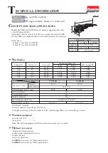
Makita GA7050R Скачать руководство пользователя страница 6

1R165

Large spiral bevel gear


6

8

R

epair

[3] DISASSEMBLY/ASSEMBLY

[3]-2. Large spiral bevel gear, Ball bearing 608ZZ, Ball bearing 6202DDW (cont.)

DISASSEMBLING

ASSEMBLING

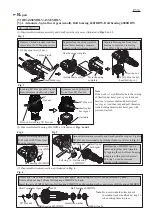
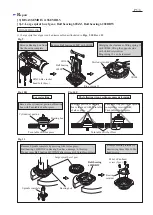
(2) Ball bearing 6202DDW can be disassembled as illustrated in 

Fig. 12A 

or 

Fig. 12B

.


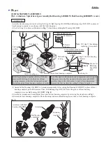
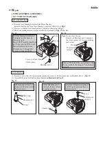
Reverse the disassembling step shown in Fig. 11, 10R and 9.

Note

: 1) Do not deform the labyrinth ring of Spindle complete when pressfitting Spindle complete to Ball bearing 

               6202DDW. (

Fig. 13

)

           2) Putting Large spiral bevel gear on 1R165, press Spindle into arbor hole of Large spiral bevel gear with Arbor 

                press. (

Fig. 14

Fig. 12A

Fig. 12B

Fig. 13

If it is difficult to remove as illustrated

in 

Fig. 13A

, remove Ball bearing 

6202DDW with the appropriate 

diameter round bar and Arbor press.  

Remove Ball bearing 6202DDW by striking Bearing box

against Work table.

Ball bearing

6202DDW 

Bearing box

Round bar 

Ball bearing 6202DDW

Labyrinth ring

of Spindle complete

Fig.14

Содержание GA7050R

Страница 1: ...cover Toolless lock nut Dust cover attachment GA7050R Accessories for 180mm angle grinder GA9050R Accessories for 230mm angle grinder 3 Weight according to EPTA Procedure 01 2003 with Side grip Wheel cover Inner flange Lock nut Net weight 3 kg lbs Power supply cord m ft Continuous Rating W Cycle Hz Input Output Max Output W 50 60 50 60 50 60 50 60 50 60 2 000 2 000 2 000 2 000 900 900 1 100 1 100 ...

Страница 2: ...r 30 100 1R258 V block Assembling Felt ring 16 to Gear housing Assembling large Spiral bevel gear to Spindle 1R269 Bearing extractor Assembling Disassembling Ball bearings 1R165 Ring spring setting tool B 4 4 Gear housing complete Apply approx 35g grease to Gear room Model No No load speed min 1 GA7050R 8 500 6 600 Spiral bevel gear 10A Spiral bevel gear 38 Spiral bevel gear 49 Spiral bevel gear 1...

Страница 3: ... INT R 32 Assemble Armature assembly and Small spiral bevel gear Tighten M7 Hex nut provisionally by turning clockwise Refer to Fig 3 Ball bearing 6201DDW can be removed together with Armature by tapping the end of Gear housing complete with a plastic hammer Felt ring 16 can be removed together with Armature Remove Carbon brushes And then remove four 5x35 Tapping screws Ball bearing 6201DDW M7 Hex...

Страница 4: ...e the Flat washer to only 0 5mm downwards Remove the Flat washer after setting Felt ring 16 in place Bottom step in Gear housing complete 26mm in outer diameter 0 5mm in thickness Flat washer as a jig Hold Gear housing complete with two V blocks and pressfit Felt ring 16 into the hole of Gear housing complete so that the felt top portion and the bottom step of Gear housing complete is in line Fig ...

Страница 5: ...tted screwdriver Enlarging the clearance of Ring spring 13 with 1R004 lift up the opposite side with slotted screwdriver Ring spring 13 can be removed Fig 9 Fig 10R Correct setting The following wrong settings causes deforming Fig 10F Fig 11 Large spiral bevel gear Bearing box Remove Bearing retainer by unscrewing three M4x16 Pan head screws 1 Large spiral bevel gear can be disassembled as illustr...

Страница 6: ...Spindle complete when pressfitting Spindle complete to Ball bearing 6202DDW Fig 13 2 Putting Large spiral bevel gear on 1R165 press Spindle into arbor hole of Large spiral bevel gear with Arbor press Fig 14 Fig 12A Fig 12B Fig 13 If it is difficult to remove as illustrated in Fig 13A remove Ball bearing 6202DDW with the appropriate diameter round bar and Arbor press Remove Ball bearing 6202DDW by ...

Страница 7: ...Release 1R268 from Pin cap carefully so that Pin cap would not be slung by Compression spring 12 Shoulder pin 11 U groove of turn table of arbor press Pin cap Note Do not reuse Pin cap Removal of Shoulder pin 11 damages the inside surface of Pin cap producing plastic dust Pin cap Compression spring 12 Pin cap Compression spring 12 Fig 16 1 Be sure to use a new Pin cap for replacement and to remove...

Страница 8: ...allation side Do not make any sags of Lead wires in Motor housing Power supply cord Lead wires of Power supply cord Route Lead wires of power supply cord between Switch and Rib Rib Rib Controller Switch Sponge sheet Pass Controller s Lead wires black red through Sponge Sheet and fix them with lead wire holder here Pull out Field lead wires black white from Motor housing and route their Field lead ...

Отзывы: