


[3] DISASSEMBLY/ ASSEMBLY
[3]-3. Replacing Armature
R
epair
P
4
/
6
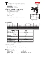
Fig. 10
Fig. 9
Fig. 12
Fig. 11
1) Loosen three 4x25 Tapping screws and remove Handle cover complete and Carbon brushes. (Fig. 9)
2) Loosen three 4x30 Tapping screws and remove the assembled parts of Gear housing, Gear housing cover and Armature
from Motor housing. (Fig. 10)
3) Remove Armature ass’y with Labyrinth rubber ring from Gear housing cover.
Armature ass’y can be disassembled as illustrated in Fig. 11. Use 1R269.
4) Take the disassembling step in reverse.
Note: Be sure to face the depressed portion of Ring 7 to Armature shaft gear end. (Fig. 12) Markings of “>PC<” “7”
are shown on the depressed portion.
4x25 Tapping
screw (3pcs.)
4x30 Tapping
screw (3pcs.)
Gear housing
cover complete
Gear housing
complete
Handle cover
complete
Motor
housing
Ring 7 (viewed
from flat side)
Ring 7 (viewed from depressed side)
Insulation
washer
Ball bearing 608VV
Ball bearing
607ZZ
Armature ass’y
Armature ass’y
Fan 52
Labyrinth
rubber ring
>PC<
7
(marking)
Armature gear
shaft end
(marking)
Fan 52
Ball bearing 608VV