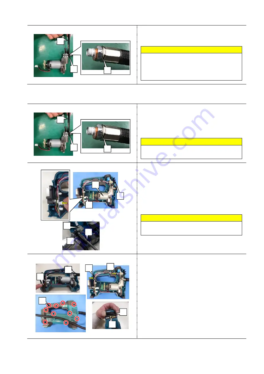
Makita DMP180 Скачать руководство пользователя страница 5


5 / 9 


Fig.4 


7


Loosen and remove Hose [1] with Wrench 10 [2] 
(781036-5). 


Note 


Only a thin wrench [2] can be inserted, so be 

careful when loosening. 


As adhesive is applied to the thread on Hose end, be 

careful when you loosen it. 


4-2-2


Assembling 


Fig.5 


1


Remove the old screw lock adhesive on the thread 

of Hose end [1], then apply a high strength 

adhesive (Loctite 272), and then tighten the joint 

portion with Wrench 10 [2] (781036-5). 


Note 

Only a thin wrench can be inserted, so be careful 

when tightening. 


Fig.6 


2


Connect Lead wires of Motor assembly [1] to the 

connector of PCB [2]. 

3


Insert the tube on the side of Pressure sensor [3] 
into Pump section. Assemble Clamp [5], then 

tighten the screw with a slotted screwdriver [4]. 

Assemble Fixed bracket [6]. 


Note 

When inserting the tube, be careful to tighten it 

because only a thin wrench can be inserted. 

4


Assemble Motor assembly [1] to Housing. 

Fig.7 


5


Assemble Mats [1] (2 pcs). Assemble the pipe 

guard of Air pipe assembly [2] to Housing. 

6


Bundle Lead wires with Cable ties [3], [4]. 

7


Align Housing R with Housing L, then tighten 

Screws 3x14 [5] (10 pcs). 

8


Assemble Swim ring adapter [6] and Ball adapter 

[7] to Fixed bracket. 


[3] 

[4] 

[2] 

[1] 

[5] 

[6] 

[7] 


[1] 

[6] 

[2] 

[3] 

[5] 

[4] 


[1] 

[1] 

[2] 


[1] 

[1] 

[2] 

Содержание DMP180

Страница 1: ...August 2020 Ver 1 OFFICIAL USE For ASC CORDLESS INFLATOR DMP180 REPAIR MANUAL...

Страница 2: ...4 1 1 Disassembling 4 4 2 Motor and Pump section 4 4 2 1 Disassembling 4 4 2 2 Assembling 5 4 3 Switch Sensor Terminal section Board 6 4 3 1 Disassembling 6 4 3 2 Assembling of Terminal section Board...

Страница 3: ...own where and how the parts are assembled and what the parts are It is also recommended to have boxes ready to keep disassembled parts by group Handle the disassembled parts carefully Clean and wash t...

Страница 4: ...2 pcs Fig 3 4 Remove Lead wires of Motor assembly 1 to release the lock by pinching the claw on the connector of PCB 2 5 Loosen the screw on Clamp 3 with a slotted screwdriver 4 then remove Tube on th...

Страница 5: ...ing Fig 6 2 Connect Lead wires of Motor assembly 1 to the connector of PCB 2 3 Insert the tube on the side of Pressure sensor 3 into Pump section Assemble Clamp 5 then tighten the screw with a slotted...

Страница 6: ...2 Remove Screw 3 10 1 then remove the following parts Switch 2 Trigger spring fixed block 3 Digital display 4 Clamp 5 Fig 10 3 Loosen Screws 3 10 1 2 pcs then remove Power on off 2 Fig 11 4 Disconnec...

Страница 7: ...Assembling of Terminal section Board Fig 12 1 When assembling PCB board 1 make sure that it is in the groove of Housing 2 Fig 13 2 Align the groove of Battery terminal 1 with the rib of Housing 1 2 1...

Страница 8: ...g 15 2 Assemble Switch 1 into two bosses 3 Assemble Digital display 2 and LED PCB 3 4 Tighten SCREW 3 10 5 carefully so as not to pinch Lead wires with Trigger spring fixed block 4 Fig 16 5 With Sprin...

Страница 9: ...2 Check by putting air into the tires of the car etc Check that the pressure rises to the specified tire pressure Measure the time from when the tire air is deflated condition to when it reaches the...

Отзывы: