


10 ENGLISH
Protections against other causes
Protection system is also designed for other causes
t h a t c o u l d d a m a g e t h e t o o l a n d a l l o w s t h e t o o l t o s t o p
automatically. Take all the following steps to clear the
causes, when the tool has been brought to a temporary
h a l t o r s t o p i n o p e r a t i o n .
1. Turn the tool off, and then turn it on again to
r e s t a r t .
2. Charge the battery(ies) or replace it/them with
recharged battery(ies).
3. Let the tool and battery(ies) cool down.
If no improvement can be found by restoring protection
system, then contact your local Makita Service Center.
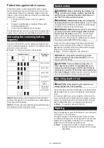
Indicating the remaining battery
capacity
Press the check button on the battery cartridge to indi
-
cate the remaining battery capacity. The indicator lamps
l i g h t u p f o r a f e w s e c o n d s .
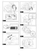
►
Fig.2:
1.
In d i c a t o r l a m p s
2.
Check button
Indicator lamps
Remaining
capacity
Lighted
Off
Blinking
7 5% t o 100%
50% t o 7 5%
25% t o 50%
0% t o 25%
C h a r g e t h e
battery.
The battery
may have
m a l f u n c t i o n e d .
NOTE:
De p e n d i n g o n t h e c o n d i t i o n s o f u s e a n d t h e
ambient temperature, the indication may differ slightly
from the actual capacity.
NOTE:
The first (far left) indicator lamp will blink when
the battery protection system works.
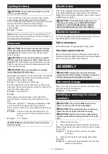
Switch action
WARNING:
Before installing the battery car-
tridge into the tool, always check to see that the
switch trigger actuates properly and returns to
the " OFF" position when released.
WARNING:
NEVER defeat the lock-off button
by taping down or some other means.
A switch with
a negated lock-off button may result in unintentional
operation and serious personal injury.
WARNING:
NEVER use the tool if it runs when
you simply pull the switch trigger without press-
ing the lock-off button.
A switch in need of repair
may result in unintentional operation and serious
personal injury. Return tool to a Makita service center
for proper repairs BEFORE further usage.
To prevent the switch trigger from being accidentally
pulled, a lock-off button is provided. To start the tool,
depress the lock-off button and pull the switch trigger.
R e l e a s e t h e s w i t c h t r i g g e r t o s t o p .
►
Fig.3:
1.
S w i t c h t r i g g e r
2.
Lock-off button
NOTICE:
Do not pull the switch trigger hard
without pressing in the lock-off button.
T h i s c a n
cause switch breakage.
CAUTION:
The tool starts to brake the cir-
cular saw blade rotation immediately after you
release the switch trigger. Hold the tool firmly to
respond the reaction of the brake when releasing
the switch trigger.
S u d d e n r e a c t i o n c a n d r o p t h e t o o l
off your hand and can cause a personal injury.
Adjusting depth of cut
CAUTION:
After adjusting the depth of cut,
always tighten the lever securely.
Loosen the lever and move the base up or down. At the
desired depth of cut, secure the base by tightening the
l e v e r .
For cleaner, safer cuts, set cut depth so that no more
than one blade tooth projects below workpiece. Using
p r o p e r c u t d e p t h h e l p s t o r e d u c e p o t e n t i a l f o r d a n g e r -
ous KICKBACKS which can cause personal injury.
►
Fig.4:
1.
L e v e r
2.
L o o s e n
3.
T i g h t e n
Sighting
Place the alignment point of the base on your intended
c u t t i n g l i n e o n t h e w o r k p i e c e .
The sight window in the base makes it easy to check
the distance between the front edge of the circular saw
blade and the workpiece whenever the circular saw
blade is set to the maximum depth of cut.
►
Fig.5:
1.
Alignment point
2.
C u t t i n g l i n e
3.
B a s e
4.
S i g h t w i n d o w
5.
Front edge of the circular
saw blade
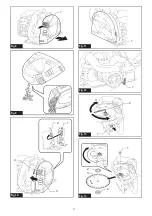
Содержание CS002G
Страница 2: ...2 1 2 3 Fig 1 1 2 Fig 2 2 1 Fig 3 1 3 2 Fig 4 3 2 4 2 5 1 Fig 5 1 Fig 6 1 2 Fig 7 ...
Страница 3: ...3 1 Fig 8 Fig 9 3 4 1 2 Fig 10 1 Fig 11 1 Fig 12 2 3 4 1 Fig 13 2 3 1 4 Fig 14 ...
Страница 5: ...5 1 2 Fig 22 ...
Страница 102: ...IDE 885965 500 1 10 2021 Makita Europe N V Jan Baptist Vinkstraat 2 3070 Kortenberg Belgium ...


