background image

8

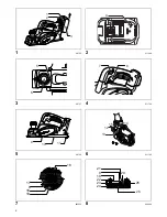
Adjusting depth of cut (Fig. 3)

Depth of cut may be adjusted by simply turning the knob 
on the front of the tool so that the pointer points the 
desired depth of cut.

Switch action (Fig. 4)

CAUTION:

• Before installing the battery cartridge into the tool, 

always check to see that the switch trigger actuates 
properly and returns to the “OFF” position when 
released.

• Do not pull the switch trigger hard without pressing the 

lock-off lever. This can cause switch breakage.

To prevent the switch trigger from being accidentally 
pulled, a lock-off lever is provided. To start the tool, slide 
the lock-off lever and pull the switch trigger. Release the 
switch trigger to stop.

WARNING:

• For your safety, this tool is equipped with lock-off lever 

which prevents the tool from unintended starting. 
NEVER use the tool if it runs when you simply pull the 
switch trigger without pressing the lock-off lever. 
Return tool a MAKITA service center for proper repairs 
BEFORE further usage.

• NEVER tape down or defeat purpose and function of 

lock-off lever.

To prevent the switch trigger from being accidentally 
pulled, a lock-off button is provided.
To start the tool, depress the lock-off button and pull the 
switch trigger. Release the switch trigger to stop.

Foot (Fig. 5)

After a cutting operation, raise the back side of the tool 
and a foot comes under the level of the rear base. This 
prevents the tool blades to be damaged.

ASSEMBLY

CAUTION:

• Always be sure that the tool is switched off and the 

battery cartridge is removed before carrying out any 
work on the tool.

Removing or installing planer blades

CAUTION:

• Tighten the blade installation bolts carefully when 

attaching the blades to the tool. A loose installation bolt 
can be dangerous. Always check to see they are 
tightened securely.

• Handle the blades very carefully. Use gloves or rags to 

protect your fingers or hands when removing or 
installing the blades.

• Use only the Makita wrench provided to remove or 

install the blades. Failure to do so may result in 
overtightening or insufficient tightening of the 
installation bolts. This could cause an injury.

For tool with conventional planer blades (Fig. 6 - 8)

To remove the blades on the drum, unscrew the 
installation bolts with the socket wrench. The drum cover 
comes off together with the blades.
To install the blades, first clean out all chips or foreign 
matter adhering to the drum or blades. Use blades of the 

same dimensions and weight, or drum oscillation/vibration 
will result, causing poor planing action and, eventually, 
tool breakdown.
Place the blade on the gauge base so that the blade edge 
is perfectly flush with the inside edge of the gauge plate. 
Place the adjusting plate on the blade, then simply press 
in the heel of the adjusting plate flush with the back side of 
the gauge base and tighten two screws on the adjusting 
plate. Now slip the heel of the adjusting plate into the 
drum groove, then fit the drum cover on it. Tighten all the 
installation bolts evenly and alternately with the socket 
wrench.
Repeat the above procedures for the other blade.

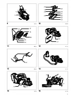
For tool with mini planer blades (Fig. 9)

1. Remove the existing blade, if the tool has been in use, 

carefully clean the drum surfaces and the drum cover. 
To remove the blades on the drum, unscrew the three 
installation bolts with the socket wrench. The drum 
cover comes off together with the blades. 

(Fig. 10)

2. To install the blades, loosely attach the adjusting plate 

to the set plate with the pan head screws and set the 
mini planer blade on the gauge base so that the 
cutting edge of the blade is perfectly flush with the 
inside flank of the gauge plate.

3. Set the adjusting plate/set plate on the gauge base so 

that the planer blade locating lugs on the set plate rest 
in the mini planer blade groove, then press in the heel 
of the adjusting plate flush with the back side of the 
gauge base and tighten the pan head screws.

4. It is important that the blade sits flush with the inside 

flank of the gauge plate, the planer blade locating lugs 
sit in the blade groove and the heel of the adjusting 
plate is flush with the back side of the gauge base. 
Check this alignment carefully to ensure uniform 
cutting.

5. Slip the heel of the adjusting plate into the groove of 

the drum. 

(Fig. 11)

6. Set the drum cover over the adjusting plate/set plate 

and screw in the three hex flange head bolts so that a 
gap exists between the drum and the set plate to slide 
the mini planer blade into position. The blade will be 
positioned by the planer blade locating lugs on the set 
plate.

7. The blade’s lengthwise adjustment will need to be 

manually positioned so that the blade ends are clear 
and equidistant from the housing on one side and the 
metal bracket on the other.

8. Tighten the three hex flange head bolts (with the 

socket wrench provided) and rotate the drum to check 
clearances between the blade ends and the tool body.

9. Check the three hex flange head bolts for final 

tightness.

10. Repeat procedures 1 - 9 for the other blade.

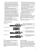
For the correct planer blade setting

Your planing surface will end up rough and uneven, 
unless the blade is set properly and securely. The blade 
must be mounted so that the cutting edge is absolutely 
level, that is, parallel to the surface of the rear base.
Refer to some examples below for proper and improper 
settings.

Содержание BKP140

Страница 1: ...ku Hobel Betriebsanleitung I Piallatrice a batteria Istruzioni per l uso NL Accuschaaf Gebruiksaanwijzing E Cepillo Inalámbrico Manual de instrucciones P Plaina a Bateria Manual de instruções DK Batteridrevet høvl Brugsanvisning GR Πλάνη μπαταρίας Οδηγίες χρήσης DKP140 DKP180 011751 ...

Страница 2: ...2 1 011755 2 011389 3 011737 4 011738 5 011739 6 011740 7 002555 8 002556 1 2 3 4 5 6 7 8 9 10 11 12 13 15 14 16 17 9 18 19 20 21 9 19 22 23 24 25 26 ...

Страница 3: ...3 9 011740 10 002565 11 002566 12 011741 13 007802 14 011757 15 011758 16 011759 12 13 15 14 27 19 28 25 29 30 31 26 32 33 33 34 30 35 18 17 19 36 37 38 39 36 40 41 ...

Страница 4: ...4 17 002580 18 011752 19 011760 20 011761 21 010183 22 003634 23 011748 24 002588 21 42 43 44 45 ...

Страница 5: ...5 25 002589 26 002590 27 001145 28 011749 29 011753 30 011750 46 47 48 49 50 51 52 53 36 53 54 53 ...

Страница 6: ...ely tightened before operation 7 Hold the tool firmly with both hands 8 Keep hands away from rotating parts 9 Before using the tool on an actual workpiece let it run for a while Watch for vibration or wobbling that could indicate poor installation or a poorly balanced blade 10 Make sure the blade is not contacting the workpiece before the switch is turned on 11 Wait until the blade attains full sp...

Страница 7: ...l operation and charge the battery cartridge when you notice less tool power 2 Never recharge a fully charged battery cartridge Overcharging shortens the battery service life 3 Charge the battery cartridge with room temperature at 10 C 40 C 50 F 104 F Let a hot battery cartridge cool down before charging it 4 Charge the battery cartridge once in every six months if you do not use it for a long per...

Страница 8: ...the gauge base so that the blade edge is perfectly flush with the inside edge of the gauge plate Place the adjusting plate on the blade then simply press in the heel of the adjusting plate flush with the back side of the gauge base and tighten two screws on the adjusting plate Now slip the heel of the adjusting plate into the drum groove then fit the drum cover on it Tighten all the installation b...

Страница 9: ... cleaner work For tool without nozzle Remove the chip cover and install the nozzle optional accessory Attach the elbow optional accessory on the nozzle of the tool by just slipping on it To remove it just pull it out For tool with nozzle Attach the elbow optional accessory on the nozzle of the tool by just slipping on it To remove it just pull it out OPERATION Hold the tool firmly with one hand on...

Страница 10: ...he new ones and secure the brush holder caps To maintain product SAFETY and RELIABILITY repairs any other maintenance or adjustment should be performed by Makita Authorized Service Centers always using Makita replacement parts OPTIONAL ACCESSORIES CAUTION These accessories or attachments are recommended for use with your Makita tool specified in this manual The use of any other accessories or atta...

Страница 11: ...esignation of Machine Cordless Planer Model No Type DKP140 DKP180 are of series production and Conforms to the following European Directives 2006 42 EC And are manufactured in accordance with the following standards or standardised documents EN60745 The technical documentation is kept by Makita International Europe Ltd Technical Department Michigan Drive Tongwell Milton Keynes Bucks MK15 8JD Engla...

Страница 12: ...issez jamais traîner d objets tels que vieux tissus chiffons cordes et ficelles dans la zone de travail 4 Prenez garde aux clous pendant la coupe Avant de travailler votre pièce inspectez la et retirez en tous les clous 5 Utilisez uniquement des lames bien affûtées Manipulez les lames avec une grande prudence 1 Bouton 2 Voyant rouge 3 Batterie 4 Étoile 5 Pointeur 6 Bouton 7 Levier de déverrouillag...

Страница 13: ... surchauffe de brûlures voire d explosion 4 Si l électrolyte pénètre dans vos yeux rincez les à l eau claire et consultez immédiatement un médecin Il y a risque de perte de la vue 5 Évitez de court circuiter la batterie 1 Ne touchez les bornes avec aucun matériau conducteur 2 Évitez de ranger la batterie dans un contenant où se trouvent d autres objets métalliques tels que des clous pièces de monn...

Страница 14: ...implement sur la gâchette sans avoir appuyé sur le levier de sécurité Renvoyez l outil à un centre de service après vente MAKITA pour le faire réparer AVANT toute autre utilisation Le levier de sécurité ne doit JAMAIS être immobilisé avec du ruban adhésif ni modifié Pour éviter tout déclenchement accidentel de la gâchette l outil est muni d un bouton de sécurité Pour démarrer l outil enfoncez le b...

Страница 15: ... la clé à douille fournie et faites tourner le tambour pour vous assurer que les extrémités du fer ne touchent pas le corps de l outil 9 Vérifiez les boulons à tête cylindrique large en effectuant un dernier serrage 10 Répétez les étapes 1 à 9 pour l autre fer Pour régler correctement le fer de rabot La surface rabotée sera grossière et inégale si le fer n est pas réglé de manière adéquate et sûre...

Страница 16: ... Insérez le garde parallèle dans l orifice à l avant de l outil Alignez le tranchant du fer sur la ligne de coupe Fig 19 Réglez le garde parallèle jusqu à ce qu il entre en contact avec le côté de la pièce à travailler puis fixez le en serrant la vis Fig 20 Lorsque vous rabotez déplacez l outil en gardant le garde parallèle parfaitement appuyé contre le côté de la pièce Autrement vous risquez d ef...

Страница 17: ... Émission de vibrations ah 3 5 m s2 Incertitude K 1 5 m s2 Modèle DKP180 Mode de fonctionnement rabotage de conifères Émission de vibrations ah 4 5 m s2 Incertitude K 1 5 m s2 ENG901 1 La valeur de l émission des vibrations déclarée a été mesurée conformément à la méthode de test standard et peut être utilisée afin de comparer des outils entre eux La valeur de l émission des vibrations déclarée pe...

Страница 18: ...en 3 Lassen Sie niemals Lappen Tücher Seile Schnüre usw im Arbeitsbereich liegen 4 Vermeiden Sie es in Nägel zu schneiden Untersuchen Sie das Werkstück vor Arbeitsbeginn auf Nägel und entfernen Sie diese ggf 5 Verwenden Sie ausschließlich scharfe Messer Gehen Sie sehr sorgfältig mit den Messern um 6 Achten Sie darauf dass die Bolzen zur Befestigung der Messer vor dem Betrieb fest angezogen sind 7 ...

Страница 19: ...ie den Betrieb umgehend Andernfalls besteht die Gefahr einer Überhitzung sowie das Risiko möglicher Verbrennungen und sogar einer Explosion 4 Wenn Elektrolyt in Ihre Augen gerät waschen Sie diese mit klarem Wasser aus und suchen Sie sofort einen Arzt auf Andernfalls können Sie Ihre Sehfähigkeit verlieren 5 Vermeiden Sie einen Kurzschluss des Akkublocks 1 Die Kontakte dürfen nicht mit leitendem Mat...

Страница 20: ...r Beschädigung des Schalters führen Um die versehentliche Betätigung des Ein Aus Schalters zu verhindern ist das Werkzeug mit einer Einschaltsperre ausgestattet Um das Werkzeug zu starten schieben Sie den Entsperrhebel und betätigen Sie den Ein Aus Schalter Lassen Sie zum Ausschalten des Werkzeugs den Ein Aus Schalter los WARNUNG Zu Ihrer Sicherheit ist das vorliegende Werkzeug mit einem Entriegel...

Страница 21: ...ssockels ausgerichtet ist Überprüfen Sie diese Positionen sorgfältig damit ein gleichmäßiger Schnittvorgang gewährleistet ist 5 Schieben Sie den Absatz der Einstellplatte in die Rille der Hobelwelle Abb 11 6 Setzen Sie die Druckplatte über die Einstell Feststellplatte und schrauben Sie die drei Sechskantflanschschrauben so fest dass zwischen Hobelwelle und Feststellplatte ein Abstand besteht um da...

Страница 22: ...e vordere Hobelsohle flach auf das Werkstück ohne dass die Hobelmesser irgendwelchen Kontakt haben Schalten Sie das Werkzeug ein und warten Sie bis die Messer ihre volle Drehzahl erreicht haben Schieben Sie dann das Werkzeug langsam vorwärts Üben Sie am Anfang des Hobelvorgangs Druck auf die vordere Hobelsohle und am Ende des Hobelvorgangs Druck auf die hintere Hobelsohle aus Das Hobeln kann durch...

Страница 23: ...e Staubbeutel Set Bogenrohr Steckschlüssel Kunststoff Tragekoffer Verschiedene Arten von originalen Akkus und Ladegeräten von Makita HINWEIS Einige der in der Liste aufgeführten Elemente sind dem Werkzeugpaket als Standardzubehör beigefügt Diese können in den einzelnen Ländern voneinander abweichen Schallpegel ENG905 1 Typischer A bewerteter Schallpegel nach EN60745 Modell DKP140 Schalldruckpegel ...

Страница 24: ...on erfolgt durch Makita International Europe Ltd Technical Department Michigan Drive Tongwell Milton Keynes Bucks MK15 8JD England 06 06 2013 Tomoyasu Kato Direktor Makita Corporation 3 11 8 Sumiyoshi cho Anjo Aichi 446 8502 JAPAN ...

Страница 25: ...imili 4 Evitare di tagliare chiodi Prima della sessione di lavoro controllare e rimuovere tutti i chiodi dal pezzo in lavorazione 5 Utilizzare solo lame affilate Maneggiare le lame con estrema cautela 1 Pulsante 2 Indicatore rosso 3 Batteria 4 Indicatore a stella 5 Indicatore di misura 6 Manopola 7 Sicura di accensione 8 Interruttore di accensione 9 Lama della piallatrice 10 Base posteriore 11 Pie...

Страница 26: ...chi sciacquare con acqua fresca e rivolgersi immediatamente a un medico Potrebbero verificarsi danni permanenti alla funzionalità visiva 5 Non cortocircuitare la batteria 1 Non toccare i terminali della batteria con materiale in grado di condurre elettricità 2 Evitare di conservare la batteria a contatto con oggetti metallici quali chiodi monete e così via 3 Non esporre le batterie all acqua o all...

Страница 27: ...re nuovamente l utensile rivolgersi a un centro di assistenza MAKITA per le necessarie riparazioni NON tentare di manomettere o di vanificare lo scopo e la funzione della sicura di accensione La sicura di accensione consente di evitare l azionamento involontario dell interruttore di accensione Per accendere l utensile premere la sicura di accensione e tirare l interruttore di accensione Per spegne...

Страница 28: ...amento su un lato e dalla staffa metallica sull altro 8 Serrare i tre bulloni a testa esagonale flangiata utilizzando la chiave a tubo in dotazione e ruotare il tamburo per controllare la distanza tra le estremità della lama e il corpo dell utensile 9 Controllare che i tre bulloni a testa esagonale flangiata siano serrati correttamente 10 Ripetere le procedure da 1 a 9 per l altra lama Per il corr...

Страница 29: ...lature come quelle mostrate nella figura utilizzare la guida laterale disponibile come accessorio Fig 18 Tracciare una linea di taglio sul pezzo in lavorazione Inserire la guida laterale nell apposito foro sulla parte anteriore dell utensile Allineare il bordo della lama con la linea di taglio Fig 19 Regolare la guida laterale fino a portarla a contatto con il lato del pezzo in lavorazione quindi ...

Страница 30: ...ENG900 1 Il valore totale delle vibrazioni somma vettoriale triassiale è determinato in conformità alla norma EN60745 Modello DKP140 Modalità di lavoro piallatura di legno dolce Emissione di vibrazioni ah 3 5 m s2 Variazione K 1 5 m s2 Modello DKP180 Modalità di lavoro piallatura di legno dolce Emissione di vibrazioni ah 4 5 m s2 Variazione K 1 5 m s2 ENG901 1 Il valore di emissione delle vibrazio...

Страница 31: ...e werkplek 4 Voorkom dat u in spijkers schaaft Inspecteer het werkstuk op spijkers en verwijder deze zo nodig voordat u ermee begint te werken 5 Gebruik uitsluitend scherpe schaafmessen Behandel de schaafmessen voorzichtig 6 Controleer dat de bevestigingsbouten van de schaafmessen stevig vastgedraaid zijn voordat u het gereedschap bedient 7 Houd het gereedschap met beide handen stevig vast 8 Houd ...

Страница 32: ... Sluit de accu niet kort 1 Raak de accupolen niet aan met enig geleidend materiaal 2 Bewaar de accu niet op een plaats waar deze in aanraking kan komen met andere metalen voorwerpen zoals spijkers munten enz 3 Stel de accu niet bloot aan water of regen Kortsluiting van de accu kan leiden tot een hoge stroomsterkte oververhitting mogelijke brandwonden en zelfs een defect 6 Bewaar het gereedschap en...

Страница 33: ...eparatie terug naar een MAKITA servicecentrum ALVORENS het verder te gebruiken U mag NOOIT de uit vergrendeling met plakband vastzetten of anderszins de werking en functie ervan te niet doen Om te voorkomen dat de aan uit schakelaar per ongeluk wordt bediend is een uit vergrendelknop aangebracht Om het gereedschap te starten drukt u de uit vergrendelknop in en knijpt u de aan uit schakelaar in Laa...

Страница 34: ...het minischaafmes zichtbaar zijn en dezelfde afstand heeft tot de behuizing aan één kant en de metalen steun aan de andere kant 8 Draai de drie zeskantflensbouten vast met de bijgeleverde dopsleutel en draai de cilinder rond om de speling te controleren tussen de rand van het minischaafmes en de behuizing van het gereedschap 9 Controleer tenslotte of de drie zeskantflensbouten stevig zijn aangedra...

Страница 35: ...en snelheid die niet zal leiden tot verstopping met houtsnippers Voor grof schaven kan de schaafdiepte groter zijn maar voor een mooi resultaat moet u de schaafdiepte verkleinen en het gereedschap langzamer vooruit bewegen Rabatten zie afb 17 Om een haakse verdieping aan te brengen zoals aangegeven in de afbeelding gebruikt u de randgeleider liniaal welke los verkrijgbaar is zie afb 18 Teken een s...

Страница 36: ...oorbescherming Trillingen ENG900 1 De totale trillingswaarde triaxiale vectorsom zoals vastgesteld volgens EN60745 Model DKP140 Gebruikstoepassing schaven van zachthout Trillingsemissie ah 3 5 m s2 Onzekerheid K 1 5 m s2 Model DKP180 Gebruikstoepassing schaven van zachthout Trillingsemissie ah 4 5 m s2 Onzekerheid K 1 5 m s2 ENG901 1 De opgegeven trillingsemissiewaarde is gemeten volgens de standa...

Страница 37: ...ela cables cuerdas y elementos similares en el área de trabajo 4 Evite cortar clavos Antes de trabajar inspeccione la pieza de trabajo y extraiga todos los clavos 5 Utilice sólo cuchillas afiladas Manipule las cuchillas con mucho cuidado 1 Botón 2 Indicador rojo 3 Cartucho de batería 4 Marca de estrella 5 Puntero 6 Pomo 7 Palanca de desbloqueo 8 Interruptor disparador 9 Cuchilla del cepillo 10 Bas...

Страница 38: ...tería 3 Si el tiempo de funcionamiento es excesivamente corto deje de utilizar la herramienta de inmediato De lo contrario existe el riesgo de sobrecalentamiento quemaduras e incluso explosión 4 Si se produce contacto ocular con electrolito enjuáguese los ojos con agua limpia y acuda de urgencia al médico Corre el riesgo de perder la visión 5 No cortocircuite el cartucho de la batería 1 No toque l...

Страница 39: ...marcha la herramienta deslice la palanca de desbloqueo y tire del disparador del interruptor Suelte el interruptor disparador para detener la herramienta ADVERTENCIA Por su seguridad esta herramienta está equipada con una palanca de bloqueo que impide que la herramienta se ponga en marcha de forma accidental NUNCA utilice la herramienta si funciona simplemente pulsando el disparador sin presionar ...

Страница 40: ... haya un espacio entre el tambor y la placa de posicionamiento para deslizar la cuchilla pequeña del cepillo hasta su posición La cuchilla será colocada por las lengüetas de posicionamiento de la cuchilla del cepillo en la placa de posicionamiento 7 El ajuste longitudinal de la cuchilla deberá realizarse manualmente para que los extremos de la cuchilla estén limpios y equidistantes del alojamiento...

Страница 41: ...igera pendiente La velocidad y la profundidad de corte determinan el tipo de acabado El cepillo eléctrico sigue cortando a una velocidad que no provoca un atasco por virutas Se puede aumentar la profundidad de corte para cortes rugosos mientras que para un buen acabado debe reducirse la profundidad de corte y se debe avanzar más lentamente Galce Rebajado Fig 17 Para realizar un corte por pasos com...

Страница 42: ...80 dB A Incertidumbre K 3 dB A El nivel de ruido durante el trabajo puede superar los 80 dB A Modelo DKP180 Nivel de presión de sonido LpA 84 dB A Nivel de potencia de sonido LWA 95 dB A Incertidumbre K 3 dB A Utilice protección para los oídos Vibración ENG900 1 Valor total de la vibración suma de vectores triaxiales determinado según el estándar EN60745 Modelo DKP140 Modo de trabajo cepillado de ...

Страница 43: ... fixação da lâmina estão bem apertados antes de utilizar 7 Segure a ferramenta com firmeza com as duas mãos 8 Afaste as mãos das peças em movimento 9 Antes de utilizar a ferramenta numa peça de trabalho deixe a a trabalhar durante algum tempo Procure a existência de vibrações ou abanamentos que possam indicar uma má fixação ou uma lâmina mal equilibrada 1 Botão 2 Indicador vermelho 3 Bateria 4 Mar...

Страница 44: ...ode criar uma grande carga eléctrica sobreaquecimento fogo e uma quebra da corrente 6 Não guarde a ferramenta e a bateria em locais onde a temperatura possa atingir ou exceder 50 C 122 F 7 Não incinere a bateria nem mesmo se esta estiver irremediavelmente danificada ou completamente gasta Pode explodir e causar um incêndio 8 Não a deixe cair e evite o choque com outros objectos 9 Não utilize uma b...

Страница 45: ...xação solto pode ser perigoso Verifique sempre se estão bem apertados Manuseie as lâminas com muito cuidado Utilize luvas ou panos para proteger os dedos ou mãos quando retirar ou instalar as lâminas Utilize apenas a chave Makita fornecida para instalar ou remover as lâminas Caso contrário poderá apertar em demasia ou insuficientemente os parafusos de fixação Isto poderá causar ferimentos Para fer...

Страница 46: ...l é cónico Quando colocar o saco do pó empurre o firmemente ao máximo para o bocal para evitar que saia durante o funcionamento Para ferramentas com bocal Encaixe o saco de pó no bocal O bocal é cónico Quando colocar o saco do pó empurre o firmemente ao máximo para o bocal para evitar que saia durante o funcionamento Fig 13 Quando o saco do pó estiver meio cheio retire o saco do pó da ferramenta e...

Страница 47: ...ssório opcional Chanfradura Fig 22 e 23 Para fazer um corte de chanfradura tal como mostrado na figura alinhe o encaixe V na base frontal com a extremidade da peça de trabalho e faça a plainagem MANUTENÇÃO PRECAUÇÃO Certifique se sempre de que a ferramenta está desligada e a bateria removida antes de efectuar operações de inspecção ou de manutenção Nunca utilize gasolina benzina diluente álcool ou...

Страница 48: ...ilizado para comparar uma ferramenta com outra O valor da emissão de vibração declarado pode também ser utilizado numa avaliação preliminar de exposição AVISO A emissão de vibração durante a utilização real da ferramenta eléctrica pode ser diferente do valor de emissão declarado dependendo da forma como a ferramenta é utilizada Certifique se de que identifica medidas de segurança para proteger o o...

Страница 49: ...t fastspændte før værktøjet tages i brug 7 Hold godt fast i maskinen med begge hænder 8 Hold hænderne på afstand af roterende dele 9 Lad maskinen køre et stykke tid før den benyttes på et arbejdsemne Hold øje med vibrationer eller slinger der kan være tegn på en forkert montering eller et dårligt afbalanceret høvljern 10 Sørg for at høvljernet ikke har kontakt med arbejdsemnet før der tændes på ko...

Страница 50: ... Veillez à ne pas laisser tomber ou heurter la batterie 9 N utilisez pas de batterie endommagée 10 Respectez les réglementations locales relatives à la mise au rebut des batteries CONSERVEZ CES INSTRUCTIONS Conseils pour assurer la durée de vie optimale de la batterie 1 Rechargez la batterie avant qu elle ne soit complètement épuisée Arrêtez toujours l outil et rechargez la batterie quand vous con...

Страница 51: ...sboltene bliver spændt enten for løst eller for stramt Det kan føre til personskader For maskine med almindelige høvljern Fig 6 8 For at fjerne tromlens høvljern skal du løsne monteringsboltene med topnøglen Tromledækslet kommer af sammen med høvljernene For at installere høvljernene skal du først fjerne alle spåner og andre fremmedobjekter der måtte sidde på tromlen eller høvljernene Brug høvljer...

Страница 52: ... kan du tilslutte en Makita støvsuger til maskinen Inden du tilslutter støvsugeren skal du afmontere spåndækslet fra maskinen Slut derefter støvsugerslangen til mundstykket ekstraudstyr som vist på figurerne For maskiner med mundstykke Hvis du vil høvle og holde arbejdsområdet rent kan du tilslutte en Makita støvsuger til maskinen Slut derefter støvsugerslangen til mundstykket som vist på figuren ...

Страница 53: ...r på holderen og indsæt høvljernene A og B så de er i kontakt med siderne C og D Stram herefter vingemøtrikkerne Fig 26 Læg slibestenen i vand i 2 til 3 minutter før slibning Hold holderen så begge høvljern er i kontakt med slibestenen for samtidig slibning i den samme vinkel Udskiftning af kulbørsterne Fig 27 Tag regelmæssigt kulbørsterne af og efterse dem Udskift dem når de er nedslidt til slidg...

Страница 54: ... at bestemme sikkerhedsforanstaltninger for beskyttelse af operatøren som er baseret på en eksponeringsvurdering for brug under faktiske forhold hvor alle anvendelsescyklussens dele inddrages som f eks antal gange maskinen slukkes og når den kører i tomgang ud over triggertiden Kun for europæiske lande ENH101 16 EF overensstemmelseserklæring Vi Makita Corporation erklærer som ansvarlig producent a...

Страница 55: ... χάσετε τον έλεγχο 3 Δεν πρέπει να αφήνετε ποτέ κουρέλια πανιά νήματα σκοινιά και παρόμοια αντικείμενα στην περιοχή εργασίας 4 Να αποφεύγετε την κοπή καρφιών Πριν από τη λειτουργία να ελέγχετε αν υπάρχουν καρφιά στο τεμάχιο εργασίας και να τα αφαιρείτε όλα αν υπάρχουν 1 Κουμπί 2 Κόκκινος δείκτης 3 Κασέτα μπαταρίας 4 Ένδειξη άστρου 5 Δείκτης 6 Κουμπί 7 Μοχλός κλειδώματος 8 Σκανδάλη διακόπτης 9 Μαχα...

Страница 56: ...οίο χρησιμοποιείται η μπαταρία 2 Μην αποσυναρμολογείτε την μπαταρία 3 Αν ο χρόνος λειτουργίας της μπαταρίας είναι υπερβολικά σύντομος διακόψτε αμέσως τη λειτουργία Αν συνεχίσετε μπορεί να έχει ως αποτέλεσμα τον κίνδυνο υπερθέρμανσης πιθανών εγκαυμάτων και ακόμη έκρηξης 4 Αν μπει στα μάτια σας ηλεκτρολύτης ξεπλύνετε με καθαρό νερό και αναζητήστε αμέσως ιατρική βοήθεια Μπορεί να χάσετε την όρασή σας...

Страница 57: ...α είναι στραμμένος στο επιθυμητό βάθος κοπής Δράση διακόπτη Εικ 4 ΠΡΟΣΟΧΗ Πριν την τοποθέτηση της μπαταρίας στο εργαλείο πάντοτε να ελέγχετε ότι η σκανδάλη διακόπτης ενεργοποιείται κανονικά και επιστρέφει στη θέση OFF όταν την αφήνετε Μην τραβάτε το διακόπτη με βία χωρίς να πιέζετε το μοχλό ασφάλισης Αυτό μπορεί να προκαλέσει το σπάσιμο του διακόπτη Για να μην τραβηχτεί ο διακόπτης κατά λάθος υπάρ...

Страница 58: ... βάση μετρητή ώστε οι γλωττίδες εντοπισμού του μαχαιριού της πλάνης στην πλάκα συγκράτησης να ακουμπούν στην εγκοπή του μικρού μαχαιριού της πλάνης και κατόπιν πιέστε προς τα μέσα τη φτέρνα της ρυθμιζόμενης πλάκας ώστε να ευθυγραμμιστεί με την πίσω πλευρά της βάσης μετρητή και σφίξτε τις βίδες κοίλης κεφαλής 4 Είναι σημαντικό το μαχαίρι να εδράζει ευθυγραμμισμένο με την εσωτερική πλευρά της πλάκας...

Страница 59: ... σκούπα της Makita στο εργαλείο που διαθέτετε Κατόπιν συνδέστε τον εύκαμπτο σωλήνα της ηλεκτρικής σκούπας στο ακροφύσιο όπως απεικονίζεται στις εικόνες Γωνία προαιρετικό αξεσουάρ Εικ 15 Η χρήση γωνιών επιτρέπει την αλλαγή της κατεύθυνσης αποβολής θραυσμάτων για την εκτέλεση των εργασιών με πιο καθαρό τρόπο Για εργαλείο χωρίς ακροφύσιο Αφαιρέστε το κάλυμμα θραυσμάτων και τοποθετήστε το ακροφύσιο πρ...

Страница 60: ...ε ένα καθαρό άκρο Εικ 25 Πρώτα χαλαρώστε τα δύο παξιμάδια πεταλούδα στον υποδοχέα και εισάγετε τα μαχαίρια A και B ώστε να έρχονται σε επαφή με τις πλευρές C και D Κατόπιν σφίξτε τα παξιμάδια πεταλούδα Εικ 26 Βυθίστε την πέτρα ακονίσματος σε νερό για 2 ή 3 λεπτά πριν από το ακόνισμα Κρατήστε τον υποδοχέα ώστε και τα δύο μαχαίρια να έρχονται σε επαφή με την πέτρα ακονίσματος για ταυτόχρονο ακόνισμα...

Страница 61: ...ΙΗΣΗ Η εκπομπή κραδασμών κατά τη διάρκεια της πραγματικής χρήσης του ηλεκτρικού εργαλείου μπορεί να διαφέρει από τη δηλωθείσα τιμή των εκπομπών ανάλογα με τον τρόπο με τον οποίο χρησιμοποιείται το εργαλείο Φροντίστε να λάβετε τα μέτρα ασφαλείας που απαιτούνται για την προστασία του χρήστη που βασίζονται σε μια εκτίμηση της έκθεσης σε πραγματικές συνθήκες χρήσης λαμβάνοντας υπόψη όλα τα μέρη του κύ...

Страница 62: ...62 ...

Страница 63: ...63 ...

Страница 64: ...ALA Makita Corporation Anjo Aichi Japan 885273A991 www makita com ...

Отзывы: