


P
3
/
8
R
epair
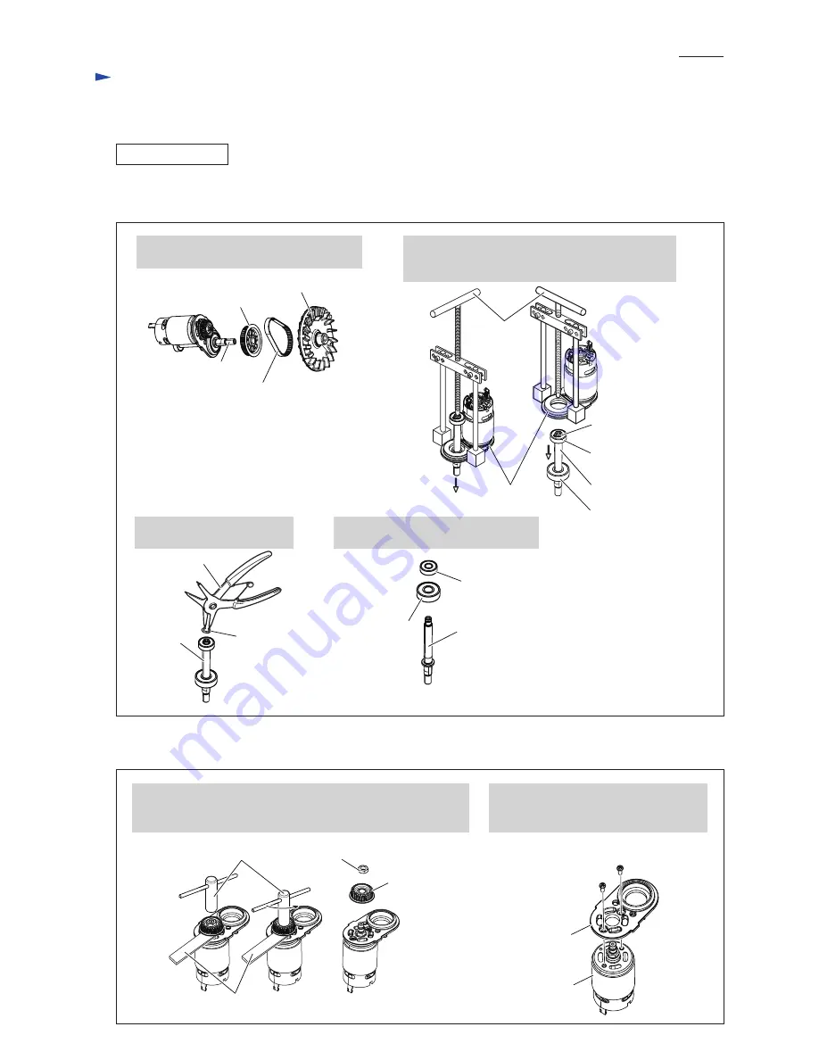
(2) Fan 88, Synchro belt 6-174, Pulley 7.5-40.3, Retaining ring S-7 and two Ball bearings are disassembled from
Spindle as drawn in
Fig. 2
.
(3) Separate DC motor from Motor bracket as drawn in
Fig. 3
.
[3] DISASSEMBLY/ASSEMBLY
[3] -1. Fan 88, DC motor and Pulleys (cont.)
DISASSEMBLING
1. Remove Fan 88, Synchro belt 6-174 and
Pulley 7.5-40.3 from Spindle.
2. Remove Spindle section (including Ball bearings
607ZZ & 629DDW and Retaining ring S-7) with
1R045 from Motor bracket.
3. Remove Retaining ring S-7
with 1R291.
4. Remove Ball bearing 607ZZ and
Ball bearing 629DDW from Spindle.
2. Remove Motor bracket from DC motor
by unscrewing two M3x8 Pan head
screws.
Fig. 2
Fig. 3
Fan 88
Spindle
Synchro belt 6-174
Pulley 7.5-40.3
Spindle
Retaining ring S-7
Retaining
ring S-7
Ball bearing 629DDW
Ball bearing 607ZZ
Motor bracket
1R045
1R291
Spindle
Ball bearing
629DDW
Ball bearing
607ZZ
Spindle
M6 Hex nut
Pulley
7.5-24.1
M3x8 Pan head
screw (2pcs.)
Motor bracket
DC Motor
1. While holding flat portion of DC motor shaft with Wrench 10,
unscrew M6 Hex nut counterclockwise with Socket wrench 10.
Pulley 7.5-24.1 is now removed from DC motor.
Socket wrench 10
Wrench 10


