N
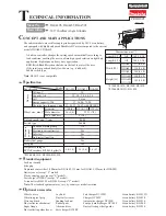
otices and required tools for assembling and disassembling
M
atters to be attended to use and handle
a.
Carefully insert ball bearing paying attention not to hurt inner races of bearing avoiding pushing
strongly inner ring and outer ring each other when ball bearing is inserted because scratch and dent on inner
race will give influence greatly on service life of bearing.
b.
Bearing check plate must be inserted with burr of the plate facing ball bearing side.
c.
Armature ball bearing at fan side must be inserted into housing with its open seal side coming to gear
side.
d.
Attaching of retainer ring must be inserted with its burr side coming to the other side of gear. It is
convenient to use retaining ring prier (ST-ZL) (Tips of the prier are bent in right angle.) to attach retaining
ring at pinion gear side.
e.
Basically machine is designed to be assembled without any shim for gear back rush adjusting but insert
the shim one by one to get optimum gear back rush when gear noise is high.
f.
Mount switch rod and switch lever with screw applying one or two drops of lock tight adhesive on the
screw threads and tighten screw to its specified position using No.1 Phillips bit driver avoiding excess
tightening torque. (Required tightening torque is from 1 kg-cm to 2kg-cm.)
g.
Be sure to confirm lever can be operated ON and OFF smoothly and surely after switch lever was
1.
Be sure to turn off power supply when tool is mounted or dismounted.
2.
Be sure to confirm complete tightening of wheel cover and lock nut for grinding wheel before
operation start.
3.
Be sure to confirm that tool does not contact with parts and body before turning on the switch.
4.
Immediately stop rotation of tool and check tool mounting state, matching of supplied power with
rating written in indication plate again when any abnormal sound, abnormal vibration, or abnormal
temperature rise is observed during tool rotating.


