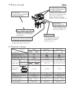
Makita 4050, 4850, 5550, 6350 Скачать руководство пользователя страница 4

R

epair

P 4 / 7 

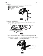
< 3 > Assembling shear blade assembly

Guide plate

Shear blade B

Shear blade A

1  Align the holes of shear blade A and B with the same 
    of guide plate.

2   Insert  spacer between shear blade A and B with aligning  its holes with
     the same of guide plate.
     For easily assembling spacer, it is recommended to insert pan head screws into
     the screw holes of guide plate in advance.

Spacer

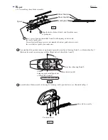
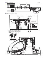
3   Turn crank until its position comes to right angle against the joint line of housing R and L,  as illustrated in Fig.5.
     Otherwise the crank can not engage with the elliptic holes of shear blade A and B. 

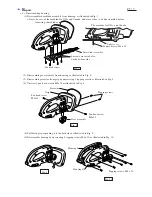
4   Assemble shear blade assembly to housing by fastening with 6 pan head screws as illustrated in Fig. 6. 

90°

Crank
being engaged with elliptic holes
of shear blade A and B. 

Joint line of housing R and L

Bottom view of housing

Fig. 5

Fig. 4

Shear blade A and B

Pan head screws

Shear blade assembly

Fig. 6

Содержание 4050, 4850, 5550, 6350

Страница 1: ...33 1 2 36 1 2 39 1 8 215 8 1 2 200 7 7 8 These new Hedge Trimmers are optimum for tough trimming works thanks to the more precise engagement of shear blade assembly with crank section And the shear b...

Страница 2: ...es such as thick branches stones etc Prevents extension cord from accidentally falling out of the plug of power supply cord Model No Specifications UH4050 UH5550 UH4850 UH6350 B 1 B 3 B 2 A 1 A 2 A 3...

Страница 3: ...teeth of helical gear approx 3g 1 The gear installing portion of motor housing approx 6g 4 Pin 8 approx 1g Pan head screw M5 x 18 Under cover 2 Unscrew 6 pan head screws marked with arrow and disasse...

Страница 4: ...ew holes of guide plate in advance Spacer 3 Turn crank until its position comes to right angle against the joint line of housing R and L as illustrated in Fig 5 Otherwise the crank can not engage with...

Страница 5: ...achine for USA and Canada 2 Disassemble gear assembly from housing as illustrated in Fig 8 3 Disassemble protector from grip by unscrewing 2 tapping screws as illustrated in Fig 8 4 Unscrew 2 pan head...

Страница 6: ...Pass lead wires between pin and wall Press lead wires into the bottom of lea holder Pin Pass lead wires toward bottom of housing L when receptacle is connected to brush assembly Bottom of housing L B...

Страница 7: ...for 220V 240V Switch A Color index of lead wires Black White Orange Yellow Purple NC NO COM Switch B Noise suppressor NC NO COM Switch A Choke coil Choke coil Insulated terminal Switch A Choke coil w...

Отзывы: