


11 ENGLISH
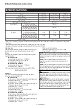
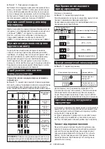
Battery indicator status
Remaining battery capacity
50% - 100%
20% - 50%
0% - 20%
Charge the battery
On
Off
Blinking
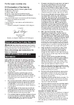
Automatic speed change function
►
Fig.5:
1.
Mode indicator
Mode indicator status
Operation mode
High speed mode
High torque mode
This tool has "high speed mode" and "high torque
mode". It automatically changes operation mode
depending on the work load. When mode indicator
lights up during operation, the tool is in high torque
mode.
Tool / battery protection system
The tool is equipped with a tool/battery protection sys-
tem. This system automatically cuts off power to the
motor to extend tool and battery life.
The tool will automatically stop during operation if the
tool or battery is placed under one of the following con-
ditions. In some conditions, the indicator lights up.
Overload protection
When the tool is operated in a manner that causes it to
draw an abnormally high current, the tool automatically
stops without any indications. In this situation, turn the
tool off and stop the application that caused the tool to
become overloaded. Then turn the tool on to restart.
Overheat protection for tool
When the tool is overheated, the tool stops automati-
cally and the battery indicator shows following state. In
this situation, let the tool cool before turning the tool on
again.
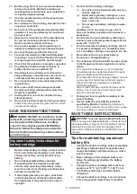
Battery indicator
Tool is overheated
On
Off
Blinking
Releasing protection lock
When the protection system works repeatedly, the tool
is locked and the battery indicator shows the following
state.
Protection lock works
Battery indicator
On
Off
Blinking
In this situation, the tool does not start even if turning
the tool off and on. To release the protection lock,
remove the battery, set it to the battery charger and wait
until the charging finishes.
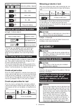
Shaft lock
CAUTION:
•
Never actuate the shaft lock when the spindle is
moving. The tool may be damaged.
►
Fig.6:
1.
Shaft lock
Press the shaft lock to prevent spindle rotation when
installing or removing accessories.
ASSEMBLY
CAUTION:
•
Always be sure that the tool is switched off and
the battery cartridge is removed before carrying
out any work on the tool.
Installing side grip (handle)
CAUTION:
•
Always be sure that the side grip is installed
securely before operation.
►
Fig.7
Screw the side grip securely on the position of the tool
as shown in the figure.
Installing or removing wheel guard
(For depressed center wheel,
multi disc / abrasive cut-off wheel,
diamond wheel)
WARNING:
•
When using a depressed center grinding wheel/
Multi-disc, flex wheel, wire wheel brush, cut-off
wheel or diamond wheel, the wheel guard must
be fitted on the tool so that the closed side of the
guard always points toward the operator.
•
When using an abrasive cut-off / diamond
wheel, be sure to use only the special wheel
guard designed for use with cut-off wheels. (In
some European countries, when using a dia-
mond wheel, the ordinary guard can be used.
Follow the regulations in your country.)
Содержание 0088381683920
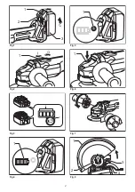
Страница 2: ...1 2 3 1 1 2 1 1 1 1 2 3 4 Fig 1 Fig 2 Fig 3 Fig 4 Fig 5 Fig 6 Fig 7 Fig 8 2 ...
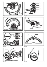
Страница 3: ...1 2 3 1 2 3 1 2 3 1 2 1 2 4 3 1 1 2 Fig 9 Fig 10 Fig 11 Fig 12 Fig 13 Fig 14 Fig 15 Fig 16 3 ...
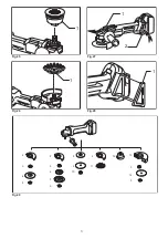
Страница 5: ...1 1 1 2 1 2 5 2 2 11 12 4 3 5 6 7 8 9 10 1 13 3 14 5 3 Fig 29 Fig 25 Fig 26 Fig 27 Fig 28 5 ...