background image

5

MakerBot Replicator

MakerBot

MakerBot Replicator Mini+

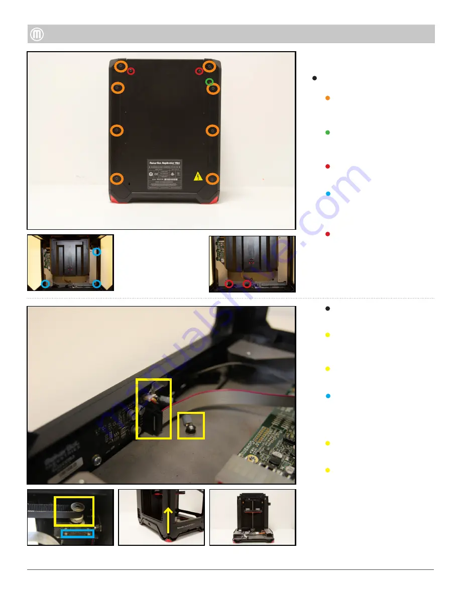
Step 5 - Remove the Housing
(optional)

Remove the following Screws:

Two (2) thread forming screws 

using a T15 driver attaching the 
Housing to the Bottom Base.

Eight (8) flathead bolts using a 

2.5mm hex driver from the edges 
of the Back Panel.

Loosen one (1) socket cap 

tensioning bolt by using a 2.5mm 

hex driver from the Back Panel.

Two (2) thread forming screws 
using a T15.

Three (3) button head screws 

using a T15 driver attaching the 
Housing to the Bottom Base.

One (1) lock nut and the ground 

wire using a 7mm nut driver.

Unplug the Camera Wire from 
the Queens PCB located at the 

bottom of the Front Panel.

Remove the Gantry Belts from the 

Motor Pulleys.

Loosen two (2) button head bolts 

located on the rear left Gantry 

Motor Mount using a 1.5mm hex 
driver.

Unplug Ribbon Cable from the 
Queens PCB.

With upward force remove the 

Outer Housing Assembly from the 
Bottom Base Assembly.

Содержание Replicator Mini+

Страница 1: ...rBot Tools Needed 1 3mm Hex Driver T10 T20 Torx Driver 2 0mm Hex Driver 1 5mm Hex Driver 2 5 mm Hex Driver Pair of thin Tweezers Small Container for Screws Color Guide Button Heads Screw Action Thread Forming Screw Socket Cap Screw Flat Head Screw ...

Страница 2: ...ving the Brooklyn PCB Removing the Power Supply Removing the Z Stage Assembly Removing the Base Cover and Electronics Cover Motor Cover Z Carriage Cover Z Stage Base Cover 3 3 3 4 4 5 6 6 7 Housing Electronics Z Stage Assembly 2 MakerBot Replicator Mini MakerBot ...

Страница 3: ... you can use a small flat head screw driver or a tool similar to it to make some space between the Outer and Inner Motor Covers Removing the Outer Motor Cover will expose the screws that attach the Inner Motor Cover to the Z Stage and Spool Assembly Step 2 Remove Z Carriage Cover Grab the Z Carriage Cover and slide upward to remove from Z stage assembly ...

Страница 4: ... can slide your fingers underneath the Base Cover and pull upwards You will feel it snap out of place slide it out of the Mini and set it aside Using 1 5mm hex driver remove the three 3 silver flat head screws attaching the Electronics cover and set aside With the Base Cover removed you now have access to the three 3 silver flat head screws attaching the Electronics Cover to the Mini Using a small...

Страница 5: ...from the Back Panel Two 2 thread forming screws using a T15 Three 3 button head screws using a T15 driver attaching the Housing to the Bottom Base One 1 lock nut and the ground wire using a 7mm nut driver Unplug the Camera Wire from the Queens PCB located at the bottom of the Front Panel Remove the Gantry Belts from the Motor Pulleys Loosen two 2 button head bolts located on the rear left Gantry M...

Страница 6: ...sembly to the bottom base Pull the Z Stage Assembly of the Housing Assembly upwards to remove using a small driver wedged between the Back Panel and Frame allows easier removal Unplug the limit switch cable from the Brooklyn PCB Unplug the Motor Wire Harness from the Brooklyn PCB Unplug the 10 pin Ribbon Cable from the Brooklyn PCB Unplug the WiFi Antenna from the Brooklyn PCB Unplug 20 pin Power ...

Страница 7: ...ni Step 8 Remove the Power Supply Remove three 3 button head screws from the rear left side of the Mini Disconnect the twenty pin connector from the Brooklyn PCB Unclip connector from plastic clips Pull Power Supply toward you to remove it out of the slot ...

Отзывы: