


8
53D0419
DV6000 Gas Fireplace
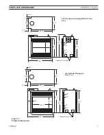
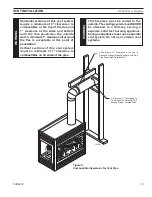
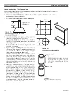
It is best to build firebox framing
aFter
the appliance is set in place. Refer to the dimensions for
your fireplace on Page 7. The framing headers may rest on the top of the firebox standoffs.
The firebox may be installed directly on a combustible floor or raised on a platform of an appropri-
ate height. Do not place firebox on carpeting, vinyl, or other soft floor coverings. It may, however,
be placed on a flat wood, plywood, particle board, or other hard surfaces. Be sure firebox rests on
a solid continuous floor or platform with appropriate framing for support. No cold air should enter
room from under the firebox.
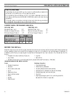
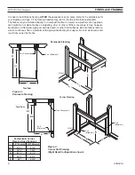
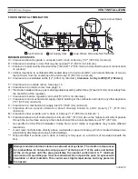
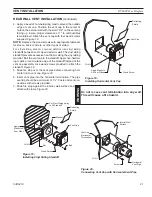
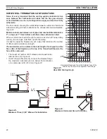
FIreplace FraMInG
peninsula & corner
Framing specifications
1/" Drywall 5/8" Drywall
A1
43
Z\x
"
43
C\,
"
A
39
M\,
"
39
C\v
"
B
41
Z\,
"
41
Z\,
"
C
C\v
"
Z\x
"
D
4"
3
M\,
"
A 2
B
A 1
D
A1
A2
C
FP2037
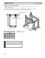
design corner framing
10/08
Gas Connection
x 4
(Minimum)
x
(Minimum)
x 4
(Minimum)
top view
corner Framing
FP037
C
A 2
B
A 1
A1
A2
C
FP2038
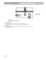
designer see thru framing
10/08
top view
x 4 (Minimum)
Gas Connection
peninsula Framing
FP038
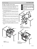
Figure 3 -
Peninsula Framing
Figure 4 -
Corner Unit Framing
(Right Hand Configuration shown)
Содержание DV6000
Страница 52: ...52 53D0419 DV6000 Gas Fireplace...
Страница 53: ...53D0419 DV6000 Gas Fireplace 53...
Страница 54: ...54 53D0419 DV6000 Gas Fireplace...