IT
14
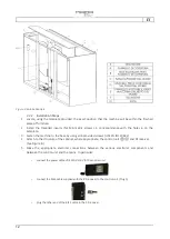
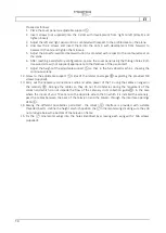
Proceed as follows:
1.
Place the cover panel on adjustable support ⑤.
2.
Insert screws (not supplied) into the 4 slots with development from right to left (slots-X) and
tighten loosely.
3.
Adjust the left and right panel until it is centered with respect to the profiled seat on the plane.
4.
Unscrew the 4 screws and insert them into the slots 4 with development from forward to
backward (Y-slots) and tighten them loosely.
5.
Adjust the panel forward and backward until it is centered with respect to the contoured seat on
the plane.
6.
After reaching a satisfactory configuration, secure the cover panel using the through holes 8 (Z).
Use wood screws (not supplied) appropriate to the thickness of the panel itself.
7.
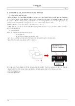
Adjust the height of the adjustable support ⑤ so that, in the fully closed machine, showing the
continuous plane.
12.
Screw to the adjustable support ⑤ sides of the lateral coverages
⑧
exploiting the provided M3
screws (supplied).
13.
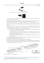
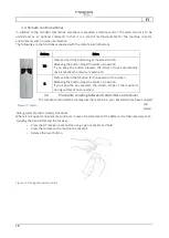
Carry out the necessary connections audio and video power of the TV using the cables arranged in
the catenary ⑩. Arrange the cables so they do not find obstacles during the movement of the
column and which do not impede the flow of the catenary in its collection guide
⑨
. In the case
where the inputs of your TV set are on the opposite side to that in which it is installed the catenary,
pass the cables between the back of the television and the column through the interface openings
VESA ⑥.
14.
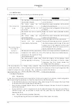
Among the different possibilities permitted -
the column ④ interface is provided with suitable
threaded inserts -
define the height at which position the ⑦ ornamental wings making sure they do
not protrude below the bottom of the television frame.
15.
Fix the ⑦ ornamental wings into the holes identified by screwing each wing with 2 M6 screws
(supplied).

