Mainstays GSH052135 Скачать руководство пользователя страница 12

7

Page 12

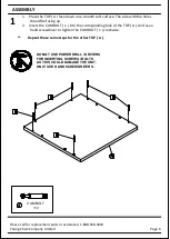
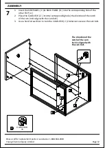
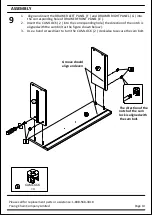
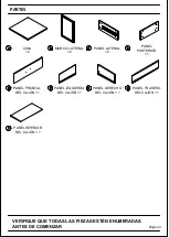
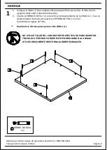
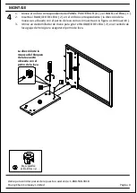
1. Insert the SIDE PANEL ( C ) & BACK PANEL ( D ) into the corresponding hole of the

           other TOP ( A ).

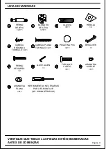
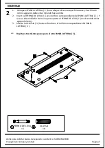
2. Place the CAM LOCK ( 2 ) into the corresponding hole ( the direction of the notch

           of the cam locks align with the cam bolt ).

3. Use a hand screwdriver to turn the CAM LOCK ( 2 ) clockwise to secure the cam bolt.

Please call for replacement parts or assistance: 1-888-568-3818

Young Chain Company Limited

CAM LOCK

×6

2

ASSEMBLY

The direction of the

notch of the cam

lock is aligned with

the cam bolt.

Содержание GSH052135

Страница 1: ...rvice s goldenspecies com Working hour Mon Fri 8 30am 5 30pm Pacific Standard Time Stock GSH052135 Lot Number _________ Date Purchased ______ ____ _____ Manufactured By Young Chain Company Limited Bin...

Страница 2: ...ssembly The shipping box provides an ideal work surface To avoid accidentally discarding small parts or hardware do not dispose of any packaging or contents of the shipping carton until assembly is co...

Страница 3: ...SIDE FRAME 2 C D E F G H I SIDE PANEL 2 BACK PANEL 1 DRAWER FRONT PANEL 1 DRAWER LEFT PANEL 1 DRAWER RIGHT PANEL 1 DRAWER BACK PANEL 1 DRAWER BOTTOM PANEL 1 VERIFY THAT ALL PARTS ARE LISTED BEFORE BE...

Страница 4: ...1 ROUND HEAD SCREW 4 1 STICKER PVC 4 1 HANDLE 1 ALLEN WRENCH 1 SMALL BOLT 2 SHORT BOLT 8 1 SPRING WASHER 8 1 FLAT WASHER 8 1 2 3 4 1 6 7 8 5 10 11 12 9 13 VERIFY THAT ALL PARTS ARE LISTED BEFORE BEGIN...

Страница 5: ...anel 4 Connect the previously tightened cam bolt with the panel connected into the cam lock 5 Using a flat head screw driver turn the cam lock halfway clockwise to secure the cam bolt 6 FAILURE TO PRO...

Страница 6: ...the TOP A And use a hand screwdriver to tighten the CAM BOLT 1 clockwise Repeat these same steps for the other TOP A ASSEMBLY Page 6 Please call for replacement parts or assistance 1 888 568 3818 You...

Страница 7: ...g hole of the SIDE PANEL C And use a hand screwdriver to tighten the CAM BOLT 1 clockwise 3 Insert the DOWEL 3 all the way into the corresponding hole of the SIDE PANEL C Repeat these same steps for t...

Страница 8: ...epeat these same steps for the other SIDE PANEL C and SIDE FRAME B ASSEMBLY Please call for replacement parts or assistance 1 888 568 3818 Young Chain Company Limited ALLEN WRENCH 1 SHORT BOLT 8 SPRIN...

Страница 9: ...he notch is aligned with the cam bolt as the figure shown below 3 Use a hand screwdriver to turn the CAM LOCK 2 clockwise to secure the cam bolt ASSEMBLY Please call for replacement parts or assistanc...

Страница 10: ...ction of the notch is aligned with the cam bolt as the figure shown below 3 Use a hand screwdriver to turn the CAM LOCK 2 clockwise to secure the cam bolt ASSEMBLY Please call for replacement parts or...

Страница 11: ...e cam locks align with the cam bolt 3 Use a hand screwdriver to turn the CAM LOCK 2 clockwise to secure the cam bolt Note Use the adjustable levelers to level the nightstand if needed Please call for...

Страница 12: ...g hole the direction of the notch of the cam locks align with the cam bolt 3 Use a hand screwdriver to turn the CAM LOCK 2 clockwise to secure the cam bolt Please call for replacement parts or assista...

Страница 13: ...e with the holes should be facing up 2 Insert the CAM BOLT 1 into the corresponding hole of DRAWER FRONT E as shown in below figures 3 Use a hand screwdriver to tighten the CAM BOLT 1 clockwise ASSEMB...

Страница 14: ...e the direction of the notch is aligned with the cam bolt as the figure shown below 3 Use a hand screwdriver to turn the CAM LOCK 2 clockwise to secure the cam bolt ASSEMBLY Please call for replacemen...

Страница 15: ...R BOTTOM PANEL I to the groove of DRAWER LEFT PANEL F and DRAWER RIGHT PANEL G All the way until into the groove of the DRAWER FRONT PANEL E ASSEMBLY Please call for replacement parts or assistance 1...

Страница 16: ...the FLAT HEAD SCREW 6 into the corresponding hole 3 Use a hand screwdriver to turn the FLAT HEAD SCREW 6 clockwise to secure the Drawer back panel ASSEMBLY Please call for replacement parts or assista...

Страница 17: ...assembly by using the ROUND HEAD SCREW 5 See figure shown below 3 Cover any visible CAM LOCK 2 using STICKER 7 as shown below This buckle is optional use only when drawer bottom panel is not steady AS...

Страница 18: ...ring pieces to the front ends as figure shown below 2 Insert the pre assembled glides on the drawer side panels into the glides on the side panel and push in to assemble the drawer ASSEMBLY Please cal...

Страница 19: ...ernes de 8 30 a m a 5 30 p m PST EE UU Correo electr nico customerservice s goldenspecies com Horario de trabajo lunes a viernes de 8 30 a M A 5 30 p M Est ndar del Pac fico Hora Valores GSH052135 Num...

Страница 20: ...as incluidas No se recomienda el uso de herramientas el ctricas para el montaje Las herramientas el ctricas pueden da ar el hardware y o partir la madera Nota No apriete completamente todos los pernos...

Страница 21: ...L LATERAL 2 PANEL POSTERIOR 1 PANEL FRONTAL DEL CAJ N 1 PANEL IZQUIERDO DEL CAJ N 1 PANEL DERECHO DEL CAJ N 1 PANEL TRASERO DEL CAJ N 1 PANEL INFERIOR DEL CAJ N 1 PARTES VERIFIQUE QUE TODAS LAS PIEZAS...

Страница 22: ...NILLO 4 1 PEGATINA PVC 4 1 RESOLVER 1 LLAVE ALLEN 1 PERNO PEQUE O 2 TORNILLO CORTO 8 1 ARANDELA MUELLE 8 1 ARANDELA PLANA 8 1 2 3 4 1 6 7 8 5 10 11 12 9 13 HERRAMIENTAS NECESARIAS PARA EL MONTAJE NO S...

Страница 23: ...nillo m s grande de la leva debe tocar el panel 3 Inserte el seguro de leva en el orificio pretaladrado en el panel La flecha mira hacia el exterior del panel 4 Conecte el perno de leva previamente ap...

Страница 24: ...llador de mano para apretar el PERNO DE LEVA 1 en el sentido de las agujas del reloj Repita estos mismos pasos para el otro CIMA A PERNO DE LEVA 12 1 MONTAJE P gina 6 Llame para solicitar piezas de re...

Страница 25: ...L LATERAL C Y use un destornillador de mano para apretar el PERNO DE LEVA 1 en el sentido de las agujas del reloj 3 Inserte la CLAVIJA 3 hasta el fondo en el orificio correspondiente del PANEL LATERAL...

Страница 26: ...sos para el otro PANEL LATERAL C y el MARCO LATERAL B LLAVE ALLEN 1 TORNILLO CORTO 8 ARANDELA MUELLE 8 ARANDELA PLANA 8 10 11 12 13 Nota El marco lateral y el ensamblaje del panel lateral tendr n izqu...

Страница 27: ...como se muestra en la figura a continuaci n 3 Utilice un destornillador de mano para girar el BLOQUEO DE LEVA 2 en el sentido de las agujas del reloj para asegurar el perno de leva BLOQUEO DE LEVA 2 2...

Страница 28: ...a como se muestra en la figura a continuaci n 3 Utilice un destornillador de mano para girar el BLOQUEO DE LEVA 2 en el sentido de las agujas del reloj para asegurar el perno de leva BLOQUEO DE LEVA 2...

Страница 29: ...va 3 Use un destornillador de mano para girar el BLOQUEO DE LEVA 2 en el sentido de las agujas del reloj para asegurar el perno de leva Nota Utilice los niveladores ajustables para nivelar la mesa de...

Страница 30: ...de la leva se alinean con el perno de la leva 3 Utilice un destornillador de mano para girar el BLOQUEO DE LEVA 2 en el sentido de las agujas del reloj para asegurar el perno de leva BLOQUEO DE LEVA...

Страница 31: ...rentando 2 Inserte el PERNO DE LEVA 1 en el orificio correspondiente del PANEL FRONTAL DEL CAJ N E como se muestra en las figuras siguientes 3 Utilice un destornillador de mano para apretar el PERNO D...

Страница 32: ...perno de leva como se muestra en la figura a continuaci n 3 Utilice un destornillador de mano para girar el BLOQUEO DE LEVA 2 en el sentido de las agujas del reloj para asegurar el perno de leva G BLO...

Страница 33: ...n la ranura del PANEL IZQUIERDO DEL CAJ N F y PANEL DERECHO DEL CAJ N G Todo el camino hasta el surco de la PANEL FRONTAL DEL CAJ N E MONTAJE MONTAJE Llame para solicitar piezas de repuesto o asistenc...

Страница 34: ...3 Utilice un destornillador de mano para girar el CABEZA PLANA TORNILLO 6 en el sentido de las agujas del reloj para asegurar el panel trasero del caj n CABEZA PLANA TORNILLO 4 6 H Aseg rese de que el...

Страница 35: ...EDONDA TORNILLO 5 Consulte la figura que se muestra a continuaci n 3 Cubra cualquier BLOQUEO DE LEVA visible 2 usando la PEGATINA PVC 7 como se muestra a continuaci n Esta hebilla es opcional sela sol...

Страница 36: ...los extremos frontales como se muestra en la figura a continuaci n 2 Inserte los rieles premontados en los paneles laterales del caj n en los rieles laterales panel y emp jelo para montar el caj n Niv...

Отзывы: