21
BA023001-en
2.4
Control unit description
The control unit consists of a control cabinet with electronic components in connection
with the corresponding operating, control and monitoring software and the operating
elements necessary for safe operation.
The electronic components consist of:
•
a ZM (central module) with a CPU module and 2 microprocessors
•
µC with logic for evaluation of the measured values and control of the motors
•
CPU module for visualisation and user interaction
•
Safety-µC for monitoring and safe switching of the outputs
•
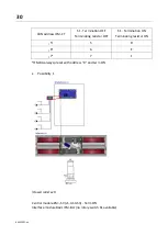
Option-dependent additional OM (option modules), e.g.
–
expansion of the I/O, if necessary (additional options of the brake tester) by
3 inputs and outputs each, address switch for setting 32 addresses (= 32 different
options supported, e.g. roller set lift, pull-down device)
•
Motor contactors
–
depending on the version, at least 1 contactor per motor as well as a motor pro-
tection switch
–
optional further contactors for additional functions such as multi-function con-
trol, star/delta start-up, 2 test speeds, etc.
•
Switching power supply 24 V DC
–
supply of the control boards and contactors
–
fuse protection via circuit breaker
•
Optional soft start module (SA)
–
to reduce the inrush current peak
–
supports the “automatic four
-
wheel drive detection” option (automatic meas-
urement in counter-rotation)
•
Optional DC brake (depending on test bench variant)
•
Protection via fuse (optional)
•
Optional circuit breaker for further options (MSD)
•
Transceiver module for radio-operated devices: FFB, RCD, PFM (optional)
Interface module
The interface module (IFM) is located in the floor assembly, separate from the control
unit in the control cabinet.
This IFM is available in two versions: a basic version (IFM-BA) with the minimum
required connections and a comfort version (IFM-CT) with all connections.
The IFM is used for analogue-digital conversion of the signals of all connected sensors
(Namur switch, range spring, load cells, etc.) and for forwarding the data via CAN bus
to the ZM. In addition, calibration values of the range spring are stored on the IFM.
Содержание CONNECT Series
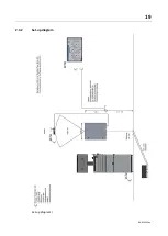
Страница 19: ...19 BA023001 en 2 3 2 Set up diagram Set up diagram I ...
Страница 20: ...20 BA023001 en Set up diagram II ...
Страница 22: ...22 BA023001 en 2 4 1 Wiring diagram ...
Страница 23: ...23 BA023001 en 2 4 2 Control cabinet structure Basic variant ...
Страница 24: ...24 BA023001 en 2 4 3 Control cabinet structure Full equipment ...
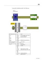
Страница 25: ...25 BA023001 en ...
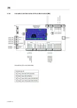
Страница 26: ...26 BA023001 en 2 4 4 Connection and termination of the central module ZM Connection of the central module ...
Страница 53: ...53 BA023001 en ...
Страница 138: ...138 BA023001 en 13 Annex 13 1 Naming convention ...


