background image

Copyright

©

 2000-2003 

MagTek

®

, Inc. 

Printed in the United States of America 

Information in this document is subject to change without notice.  No part of this document may 
be reproduced or transmitted in any form or by any means, electronic or mechanical, for any 
purpose, without the express written permission of MagTek, Inc. 


MagTek is a registered trademark of MagTek, Inc. 
 
MICRImage is a trademark of MagTek, Inc. 
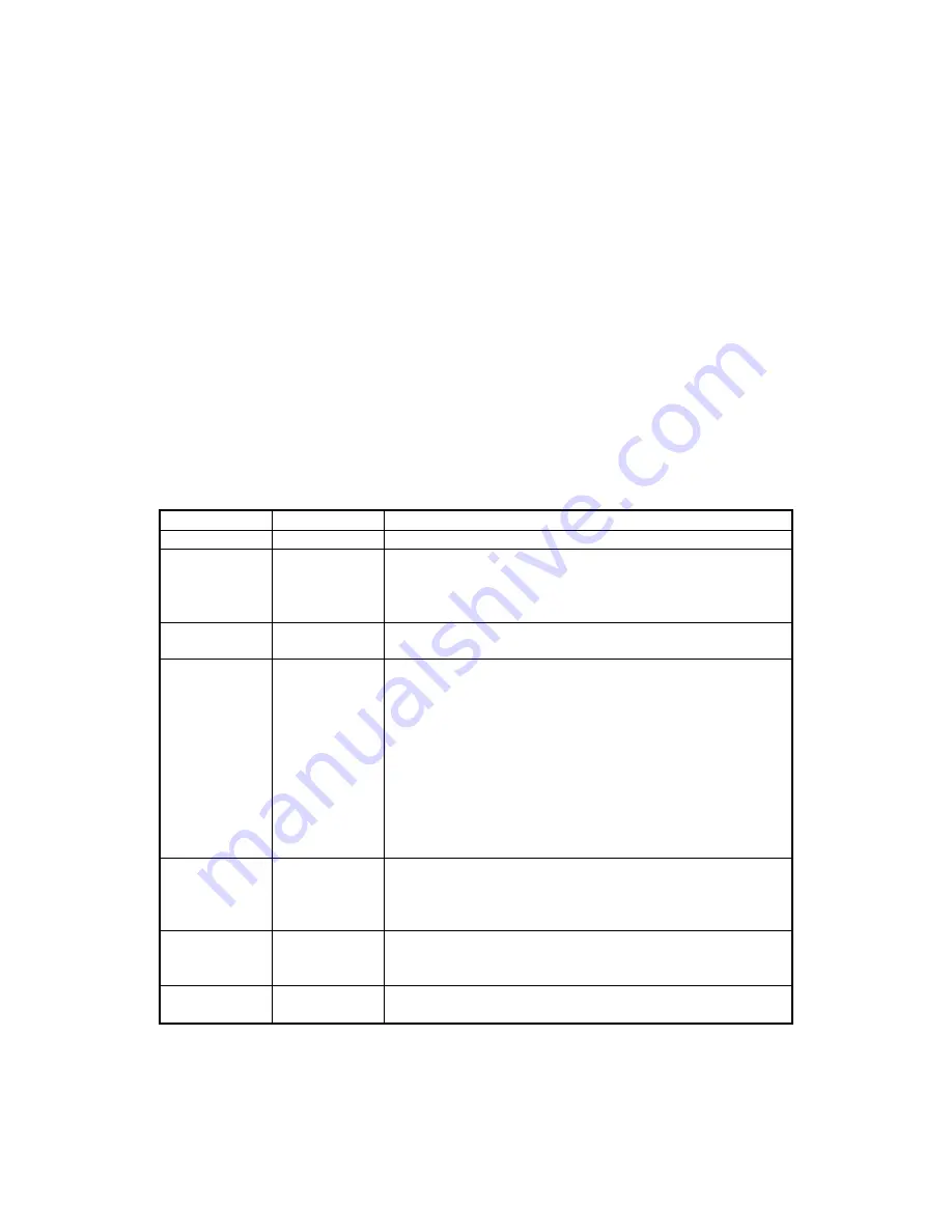


REVISIONS 


Rev Number 

Date 

Notes 

20 Oct 00 

Initial Release 

27 Jun 01 

Front Matter:  Changed Limited Warranty to exclude 
Scan Bar. Sec 2: Added two cabling diagrams, Terminal 
and Auxiliary Device and PC and Net Connection.   
Moved Check Path Cleaning to Sec 3.   

2 Aug 01 

Front Matter, Agency page:  Editorial changes to CE and 
UL/CUL. 

12 Oct 01 

Front Matter:  New Figure 1-1, added MSR.  
Section 1:  Added description and P/N of MSR.  New 
Table 1-1, added list of cables. Table 1-2 changed 
document size from 9” to 8.5” max..  Editorial Changes. 
Section 2:  New Figure 2-1, added MSR and editorial 
changes. 
Section 3: New Figure 3-2, added MSR orientation 
Modified Figures 3-3 and 3-4, added new procedure for 
opening and closing unit for imaging bar. New Figures 3-
5 and 3-6 for new cleaning procedures. Modified Figure 
3-7 for closing. 

9 May 02 

Sec 1:  Added 2 more Configurations and clarified 
features; added 1 more Cable; clarified Spec for 
interface option.  Sec 2:  changed Fig 2-4 and 2-5 for 
clarification.  Sec 3: Clarified Card Reading Procedure. 

16 Jul 02 

Front Matter: Added FCC, Part 68 Notice. Changed 
MagTek to MagTek throughout.  Sec 2:  Changed title of 
Fig 2-5 from “Net” to “Ethernet or Modem.” 

27 May 03 

Front Matter: added ISO line to logo, changed Tech 
Support phone number, added new warranty statement 


ii

Содержание 22410002

Страница 1: ...TECHNICAL REFERENCE MANUAL Manual Part Number 99875173 Rev 7 MAY 2003 REGISTERED TO ISO 9001 2000 20725 South Annalee Avenue Carson CA 90746 Phone 310 631 8602 FAX 310 631 3956 Technical Support 651 4...

Страница 2: ...Front Matter New Figure 1 1 added MSR Section 1 Added description and P N of MSR New Table 1 1 added list of cables Table 1 2 changed document size from 9 to 8 5 max Editorial Changes Section 2 New F...

Страница 3: ...ject to abnormal working conditions This warranty does not apply when the malfunction results from the use of the Product in conjunction with ancillary or peripheral equipment where it is determined b...

Страница 4: ...ation of this device is subject to the following two conditions 1 This device may not cause harmful interference And 2 This device must accept any interference received including interference that may...

Страница 5: ...thout a decimal point e g 03 is a REN of 0 3 If the MICRImage with internal modem equipment causes harm to the telephone network the telephone company will notify you in advance that temporary discont...

Страница 6: ...NDICATORS 11 CLEANING 11 Opening the Unit 11 MSR Cleaning Card 11 Cleaning Check Path and Imager 12 Closing the Unit 14 SECTION 4 TROUBLESHOOTING GUIDE 15 REQUIREMENTS 15 SET UP 15 APPENDIX A INTERFAC...

Страница 7: ...al Magnetic Swipe Reader Orientation 10 Figure 3 3 Opening the Unit 12 Figure 3 4 Cleaning Check Path and Imager 12 Figure 3 5 Activating the Cleaning Swab 13 Figure 3 6 Cleaning the Imager 13 Figure...

Страница 8: ...Figure 1 1 MICRImage Check Reader with MSR viii...

Страница 9: ...The MICRImage Reader has the capability of supporting some hardware handshaking signals An optional three track MSR autodiscriminates different card formats ISO International Standards Organization C...

Страница 10: ...Host Interface Cables See Table 1 1 AC Power Adapter with Cable 120VAC to 12 VDC 1 5 Amp Part Number 64300090 MICRbase Program Part Number 22000021 Sample Checks Part Number 96530005 Cleaning Cards P...

Страница 11: ...on 200 dpi MICR fonts supported E13 B CMC 7 Interface Options Primary RS 232 RS 485 IBM 4683 Secondary RS 232 Ethernet 10 Base T V 34 Modem MECHANICAL Dimensions Length 9 0 Width 3 9 Height 6 0 Weight...

Страница 12: ...MICRImage Check Reader 4...

Страница 13: ...Check Reader is described below Figure 2 1 shows the unit with the MSR LED Check Path Card Path Easy Access Latch Figure 2 1 MICRImage with MSR REQUIREMENTS The following is required for the Installa...

Страница 14: ...ure 2 2 DB25 Connection 2 Connect the DB9 connector to the PC as shown in Figure 2 3 2 4 and 2 5 3 Connect RJ45 Jack to the network connection as indicated in Figure 2 5 4 On the AC power adapter conn...

Страница 15: ...6 inches of a computer monitor or power supply These devices may cause undesirable interference with the check reading operation For a single PC install the MICRImage cables as shown in Figure 2 3 MIC...

Страница 16: ...P N 22410306 Terminal RS 232 Peripheral Figure 2 4 Cabling Terminal and Auxiliary Device For a PC and Network connection install the MICRImage cables as indicated in Figure 2 5 MICRImage 12 VDC Power...

Страница 17: ...k forward 3 When the MICRImage detects the presence of the check the motor will turn on At this time gently urge the check forward until the unit grabs the check When this happens release the check Th...

Страница 18: ...unit and toward the wide color stripe on the MRS as indicated in Figure 3 2 2 Slide the card in one motion from the top of the unit down through the slot as indicated in the illustration 3 After the c...

Страница 19: ...does not run FLASH RED Motor sensor blocked motor does not run Refer to Section 4 Troubleshooting Guide CLEANING Clean the outside of the MICRImage unit with a soft damp cloth and wipe with a dry clo...

Страница 20: ...hown in Figure 3 4 check the path for debris To clean turn the unit over and tap gently on the bottom Imager Easy Access Latch Alignment Pin Alignment Hole Easy Access Latch Pull Latch Up Then Back Fi...

Страница 21: ...he plastic tube until you hear a snap Figure 3 5 Activating the Cleaning Swab 4 Wait until the liquid moves into the sponge tip It should be damp when touched 5 When the tip of the swab is damp clean...

Страница 22: ...e Alignment Pin And Hole Match Alignment Pin Alignment Hole 1 Hold the unit as shown in Figure 3 7 Push the covers together while ensuring alignment of the pin and hole 2 The unit is properly closed w...

Страница 23: ...ector of the RS232 cable into the MICRImage Reader 2 Plug the DB9 connector of the RS232 cable into the PC 3 Power on the MICRImage Reader 4 Run the MICRbase program on the PC 5 Start trouble shooting...

Страница 24: ...outlet on the wall and the switch on the strip is turned on AC adapter is defective replace the AC adapter Determine if any of the conditions described above are true If yes rectify and continue to s...

Страница 25: ...gnals are enabled Use SET MICR to change this option to IGNORE Determine if any of the conditions described above are true If yes rectify and continue to step 02 If no continue to step 13 06 Read erro...

Страница 26: ...arameters do not match Verify that the communication parameters of the MICRImage Reader match the parameters of the PC Use MICRbase to verify change the communication parameters Determine if the condi...

Страница 27: ...nsor may be blocked by dust build up or foreign debris see Figure 5 1 Use forced air to clean the sensor Power off the MICRImage Reader and then power on again observe the LED indicator If the LED ind...

Страница 28: ...Cable problem Possible causes for this problem are Loose connection the cable connector on the PC or the MICRImage Reader may be loose Make sure that both connectors are tightly connected Damaged cab...

Страница 29: ...needs further analysis testing and possibly repair Please contact the MagTek Help Desk at 888 624 8350 and make arrangements to send the unit back to MagTek Include a detailed description of the prob...

Страница 30: ...MICRImage Check Reader 22...

Страница 31: ...MICRImage Reader to the Host 11 TXD 3 TXD Transmitted Data Transmits data from the Host to the MICRImage Reader 21 RXD 5 GND Ground 16 GND 7 RTS Request to Send Sends a signal to the MICRImage Reader...

Страница 32: ...MICRImage Check Reader 24...

Страница 33: ...T 04 24 D 44 d 64 ENQ 05 25 E 45 e 65 ACK 06 26 F 46 f 66 BEL 07 27 G 47 g 67 BS 08 28 H 48 h 68 HT 09 29 I 49 i 69 LF 0A 2A J 4A j 6A VT 0B 2B K 4B k 6B FF 0C 2C L 4C l 6C CR 0D 2D M 4D m 6D SO 0E 2E...

Страница 34: ...MICRImage Check Reader 26...

Страница 35: ...is used in the US Canada Australia United Kingdom Japan India Mexico Venezuela Colombia and the Far East The CMC 7 set is used in France Spain other Mediterranean countries and most South American cou...

Страница 36: ...Nonnumeric Characters CMC 7 Character MICRImage Reader Output SI A SII B SIII C SIV D SV E CHECK LAYOUTS Personal checks with MICR fields are shown in Figure C 1 Business checks are shown in Figure C...

Страница 37: ...the numbers below the checks on the illustration and represent the 4 MICR fields 1 Transit Field The Transit field is a 9 digit field bracketed by two Transit symbols The field is subdivided as follow...

Страница 38: ...umber and or a transaction code Note that an On Us symbol must always appear to the right of the account number 3 Amount Field The Amount field is a 10 digit field bracketed by Amount symbols The fiel...

Отзывы: