2
Specifications
Output:
0 to 80 psi
Maximum supply pressure:
250 psi
Input:
4 to 20 madc
Minimum supply pressure:
5 psi above maximum required, 35 psi minimum
Flow Capacity:
40 scfm at 100 psi supply and 20 psi set
Exhaust Capacity:
0.5 scfm at downstream pressure
5 psi above set point
Shock and Vibration Effect
on Output Pressure:
Negligible at 4 G between 5 to 200 Hz
Brake Pressure Gage:
2 in. dial, 0 to 100 psi
Filters (2):
3 micron with automatic drain
0.01 micron with automatic drain
Maintenance
The dripwell is drained automatically on both filters depending upon the flow through the filters and
pressure drop in the filters.
To change a filter element, unscrew metal bowl, remove element retainer; element can now be removed.
Place new element on retainer and place whirl disc on top of the element. Screw retainer back into head
making sure whirl disc fits over shoulder on head. Screw bowl into head hand tight. Bowl can be
cleaned in kerosene, gasoline or similar solvent.
Recommended replacement of the filter element is once a year under normal supply air condition. More
frequent replacement required if the supply air contains a significant amount of oil or water.
Repair
It is recommended that transducer section failures be returned to the factory for repair. But in the case
when internal clogging occurs due to improper filtering of the supply air, the orifice can be cleaned
without removing the unit from its mounting or plumbing. Turn off the supply air. Unscrew and remove
the orifice assembly. Clean the orifice through the side of the orifice assembly using a wire that has a
smaller diameter than 0.015 in. Shake out any loose particles inside of the orifice assembly. Screw
orifice assembly back into unit.
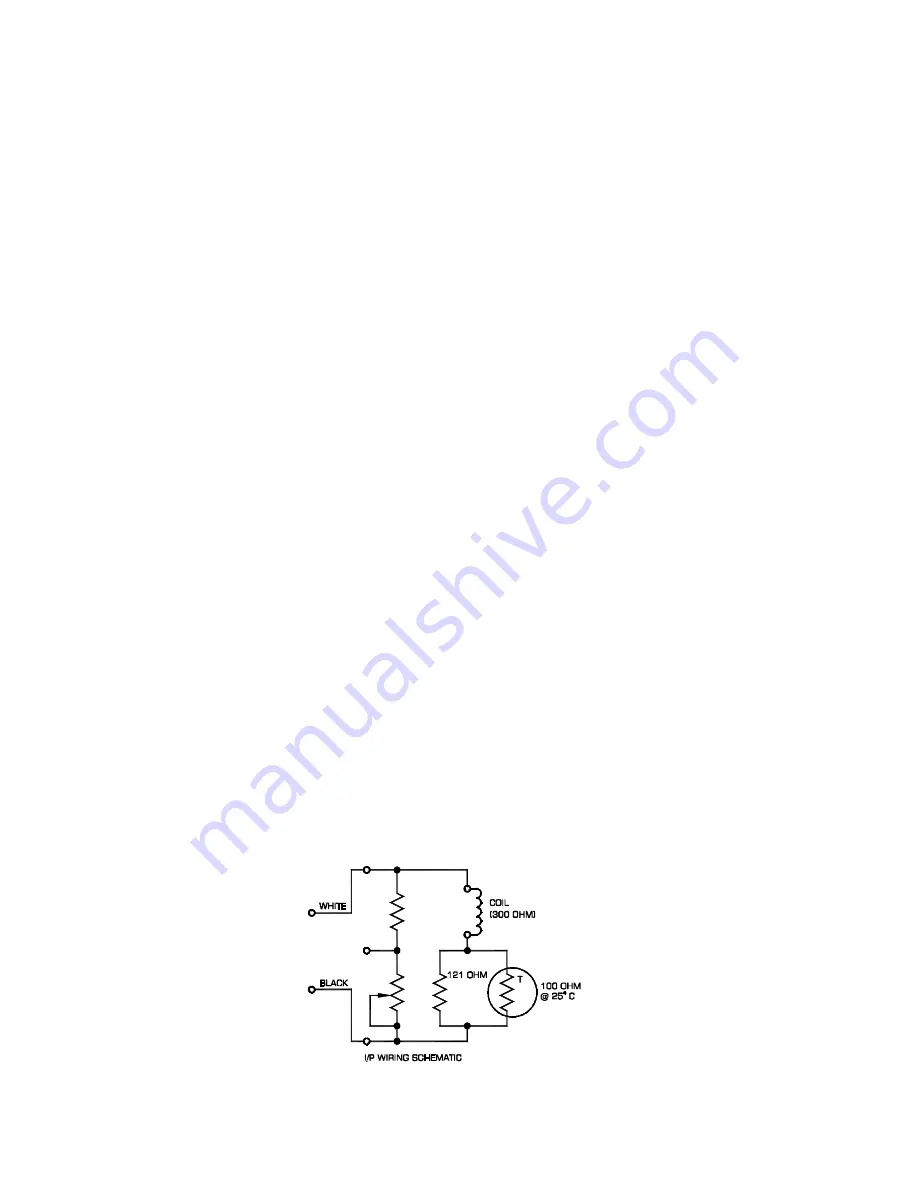
Wiring Diagram


