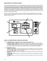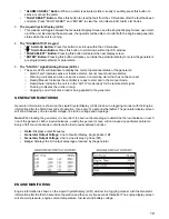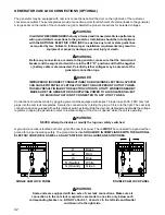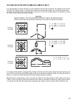
28
MDC CONTROLLER (MDC) – HISTORY
The Magnum Digital Controller (MDC) controller stores a record of each important event into the history file of the
controller. The history file seats 118 records. When the history file is full, the oldest records are removed.
ADJUSTING THE DISPLAY BACK LIGHTING
The brightness on the Liquid Crystal Display (LCD) window may be adjusted by the operator whenever the Magnum
Digital Controller (MDC) is powered up.
Note: Anytime an “*” is displayed on the LCD window, the text or set point cannot be changed without the use of a
password. Contact Magnum Products Technical Support for assistance.
1. Press and hold “Enter,” then press “
S
” or “
T
” on the Diagnostics keypad to increase or decrease the
brightness as needed.
2. Release the “Enter” button when the desired brightness is attained.
No.
Record Structure
Abbreviation
Historical value
1
AIM1
IG-IOM, IGS-PTM Analog input 1 value (when configured IG-IOM, IGS-PTM)
2
AIM2
IG-IOM, IGS-PTM Analog input 2 value (when configured IG-IOM, IGS-PTM)
3
AIM3
IG-IOM, IGS-PTM Analog input 3 value (when configured IG-IOM, IGS-PTM)
4
AIM4
IG-IOM, IGS-PTM Analog input 4 value (when configured IG-IOM, IGS-PTM)
5
BIM
IG-IOM, IGS-PTM Binary inputs (when configured IG-IOM, IGS-PTM)
6
BIN
Binary inputs IL-NT
7
BOM
IG-IOM, IGS-PTM Binary outputs (when configured IG-IOM, IGS-PTM)
8
BOUT
Binary inputs IL-NT
9
Date
Date of historical event in format DD/MM/YY
10
EngT
IL-NT Analog input 2 value (default Water temperature)
11
FC
ECU alarm FailureCode
12
FLvl
IL-NT Analog input 3 value (default Fuel level)
13
FMI
ECUalarm Failure Mode Identifier
14
Gfrg
Generator frequency
15
Ig1
Generator current L1
16
Ig2
Generator current L2
17
Ig3
Generator current L3
18
LChr
Character of the load
19
Num
Number of historical event
20
OilP
IL-NT Analog input 1 value (default Oil pressure)
21
PF
Generator PF
22
Pwr
Generator active power
23
Reason
Event specification
24
RPM
Engine Speed
25
Time
Time of historical event in format HH:MM:SS
26
Ubat
Battery voltage
27
Vg1
Generator voltage L1
28
Vg2
Generator voltage L2
29
Vg3
Generator voltage L3
Содержание MMG 150
Страница 1: ...DIESEL GENERATOR MMG150 MMG170 MMG235 OPERATING MANUAL ...
Страница 13: ...13 SERVICE LOCATIONS ...
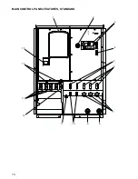
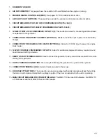
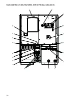
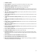
Страница 14: ...14 MAIN CONTROL PANEL FEATURES STANDARD 1 2 3 4 7 8 9 10 11 12 13 15 14 5 6 ...
Страница 52: ...REV F PART NO 26277 01 11 10 ...

