background image

PARTS LIST FOR MI-91703 / MI-91700

PARTS NO.

DESCRIPTION 

SPECIFICATION

Q'TY

MI-91703-98

PHILLIPS HEAD SCREW

3/16X1/2"

4

MI-91703-99

PLASTIC TUBE

1

MI-91703-100

LOCK-OUT SWITCH KEY

2

MI-91703-101

HANDWHEEL HANDLE

1

MI-91703-103N

SLEEVE BEARING

2

MI-91703-104N

GUIDE BRACKET

1

MI-91703-105

SET SCREW

1/4 "

6

MI-91703-106

PIN 

1

MI-91703-107N

BLADE GUARD RACK

1

MI-91703-108N

BLADE GUARD PINION

1

MI-91703-110

BUTTON HEAD SCREW

6X30MM

2

MI-91703-111

EXTERNAL RETAINING RING

S10

2

MI-91703-112

BAKELITE BLOCK

4

MI-91703-113

BUTTON HEAD SCREW

4X12MM

4

MI-91703-114

BLADE GUIDE MOUNT

4

MI-91703-115

SET SCREW

4MMX4MM

4

MI-91703-116

BEARING SHAFT

4

MI-91703-117

BEARING

10

MI-91703-118

FLAT WASHER

3/8 "

8

MI-91703-119

CAP SCREW

8X55 MM

4

MI-91703-120

BLADE GUIDE BRACKET

2

MI-91703-121

BLADE GUIDE BRACKET SHAFT

2

MI-91703-122

HEX NUT

M6

2

MI-91703-123

SET SCREW

6X 50 MM

2

MI-91703-124

ADJUSTMENT NUT

2

MI-91703-125

CAP SCREW

5/16X1 1/4"

1

MI-91703-126

SLIDE BLOCK

1

MI-91703-127N

HEX BLOCK 

1

MI-91703-128N

BLADE GUARD

1

MI-91703-129

DEPTH SCALE POINTER

1

MI-91703-130

BLADE GUIDE BRACKET HOLDER 

1

MI-91703-131

SUPPORT SHAFT(L)

1

MI-91703-132

THUMB SCREW

1/4” X 3/4”

2

MI-91703-133

EXTERNAL RETAINING RING

S13

1

MI-91703-134

WORM BUSHING

1

MI-91703-135

EXTERNAL RETAINING RING

S17

1

MI-91703-136

HANDWHEEL

1

MI-91703-137

WORM GEAR

1

MI-91703-138

GEAR SHAFT

1

MI-91703-139

GEAR  

1

MI-91703-140N

DEPTH SCALE

1

MI-91703-141

BUSHING

4

MI-91703-142

HANDWHEEL HANDLE

1

MI-91703-143

HEX. BOLT

M5 x 16

4

MI-91703-144

FLAT WASHER

3/16” - 12”

4

MI-91703-145

PIN 

5 x 14mm

2

MI-91703-146

INTERNAL RETAINING RING R28

4

MI-91703-147

BLADE GUIDE EXTENSION BRACKET

1

MI-91703-202

HEX BOLT 

5/16X1"

1

Содержание MI-91703

Страница 1: ...MODEL NO MI 91703 MI 91700 OPERATING MANUAL...

Страница 2: ...te Approved glasses have Z87 printed or stamped on them 4 REMOVE ADJUSTING KEYS AND WRENCHES Form habit of checking to see that keys and adjusting wrenches are removed from tool before turning it on 5...

Страница 3: ...cutting operation is dusty Everyday eyeglasses only have impact resistant lenses they are NOT safety glasses 14 SECURE WORK Use clamps or a vise to hold work when practical It s safer than using your...

Страница 4: ...arts mounting and any other conditions that may affect its operation A guard or other part that is damaged should be properly repaired or replaced 22 DIRECTION OF FEED Feed work into a blade or cutter...

Страница 5: ...den slip could allow the hand to contact the blade 6 Do not attempt to saw stock that does not have a flat surface unless a suitable support is used 7 Make sure blade is not contacting the workpiece b...

Страница 6: ...the band saw from unauthorized operation and to avoid accidental starting by children or other not qualified to use the use of padlock is required To lock out the on off switch open the padlock insert...

Страница 7: ...nt of the electric cord or plug is necessary do not connect the equipment grounding conductor to a live terminal Check with a qualified electrician or service personnel if the grounding instructions a...

Страница 8: ...etch D in Figure 1 The tool has a grounding plug that looks like the plug illustrated in Sketch D in Figure 1 Make sure the tool is connected to an outlet having the same configuration as the plug No...

Страница 9: ...ing Volta Total length of cord in feet 120V 240V 25ft 50ft 100ft 150ft 50ft 100ft 200ft 300ft Not More More Than Than AWG 0 6 6 10 10 12 12 16 18 16 16 14 18 16 14 12 16 16 14 12 14 12 Not Recommended...

Страница 10: ...ure proper and safe operation These symbols are used on the machine to indicate points or instances of specific danger to operating personnel Make sure to memorize these symbols and bring them to the...

Страница 11: ...11 A Bandsaw Machine B Door Knob C Guide Post Handwheel D Blade Guide Support E Blade F Fence G Working Table H Brake Foot I Blade Tension Handle Wheel J Switch...

Страница 12: ...throat 17 1 2 Maximum width of cut 17 1 2 Maximum depth of cut 16 Dust collection ports 4 2PCS Base dimensions 98CM 50CM Blade length 3700mm Blade speed 600 840RPM Bearings sealed and permanently lubr...

Страница 13: ...bed below Whichever option you choose it is necessary to level your machine with a precision level SELECTION OF LOCATION Requirement of operating environment the operating temperature for this machine...

Страница 14: ...e must be adequate enough that operations can be performed safely Shadows glare or strobe effects that may distract or impede the operator must be eliminated TRANSPORTATION Carefully check over the ma...

Страница 15: ...cting the power wires make sure the voltage between the machine and your factory power source is the same 2 Take out the electrical cover at the electrical control box outside 3 Connect the power wire...

Страница 16: ...ment rod and adjust the blade guides until the edges of the bearings are 1 16 behind the blade gullets as illustrated in Figure 2 Note The 1 16 spacing is ideal although with larger blades it may not...

Страница 17: ...er guides All though the lower guides are set up a little differently the concept is the same 8 Loosen the support bearing thumbscrew A 9 Place a 0 016 feeler gauge between the support bearing and the...

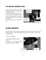
Страница 18: ...om the top of the workpiece 4 Lock the guide post in place with the lock knob BLADE TENSION Bandsaw blades stretch when tensioned and during operation Eventually an over stretched blade will break To...

Страница 19: ...d circuit 4 Refer to motor nameplate for correct voltage Motor overheats 1 Motor overloaded 2 Air circulation through the motor restricted 1 Reduce load on motor 2 Clean out fan and fan cover Machine...

Страница 20: ...N N...

Страница 21: ...126 50 51 125 124 48 108N 7 50 51 41 90 129 123 122 121 120 114 115 116 50 132 41 40 111 117 110 112 119 117B 118 113 114 115 116 116 115 115 114 111 117 121 120 131 130 50 51 7 50 119 118 141 114 13...

Страница 22: ......

Страница 23: ......

Страница 24: ...EARING 4 MI 91703 21 UPPER WHEEL 1 MI 91703 22 WHEEL WASHER 2 MI 91703 23 LOCK WASHER 3 8 18 MI 91703 24 HEX BOLT 3 8 X3 4 2 MI 91703 25N SAW BLADE 145 5 8 1 MI 91703 26 UPPER DOOR 1 MI 91703 27 HINGE...

Страница 25: ...W 1 MI 91703 70 MOTOR MOUNTING PLATE 1 MI 91703 71 MOTOR M1 3HP 220V 1 PH 16A 1 MI 91703 71 A MOTOR M2 3HP 220 440V 3PH 8 4A 4 2A 1 MI 91703 71 B MOTOR M3 3HP 600V 3 PH 3 5A 1 MI 91703 72 WINDOW 1 MI...

Страница 26: ...03 120 BLADE GUIDE BRACKET 2 MI 91703 121 BLADE GUIDE BRACKET SHAFT 2 MI 91703 122 HEX NUT M6 2 MI 91703 123 SET SCREW 6X 50 MM 2 MI 91703 124 ADJUSTMENT NUT 2 MI 91703 125 CAP SCREW 5 16X1 1 4 1 MI 9...

Страница 27: ...SCREW 1 4 3 MI 91703 231 AUXILIARY FENCE 1 MI 91703 232 HEX NUT 1 4 3 MI 91703 233 TABLE ALIGNMENT PIN 1 MI 91703 234 HEX BOLT 1 4 X 3 4 4 MI 91703 235 RIP FENCE STORAGE BRACKET 1 MI 91703 236 MITER G...

Страница 28: ...1 MAIN BASE 1 4 1 MI 91703 A2 FLAT WASHER 1 4 4 MI 91703 A3 LOCK WASHER 1 4 x5 8 4 MI 91703 A4 HEX BOLT 5 16 4 MI 91703 A5 HEX NUT 1 MI 91703 A6 T TYPE BASE 5 16 1 MI 91703 A7 FLAT WASHER 5 16 12 MI 9...

Отзывы: