background image

10

MAINTENANCE 

MAGNUM INDUSTRIAL 20" HEAVY-DUTY PLANER 

MI-31550 / MI-31552 / MI-31553

19

WARNING!

Before performing any maintenance, ensure the power switch is OFF and the power cord is unplugged

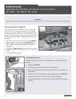
REPLACING GEARBOX OIL

You should change the gearbox oil after every 2,500 hours of 
operation. Use 80W-90 gear oil. To change the gearbox oil, 
follow these steps:

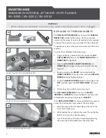
1.  The gearbox is located behind the panel on the right 

side of the planer. To remove the panel, first remove the 
handwheel. Next unthread and remove the feed speed 
adjustment knob. Then remove the panel.

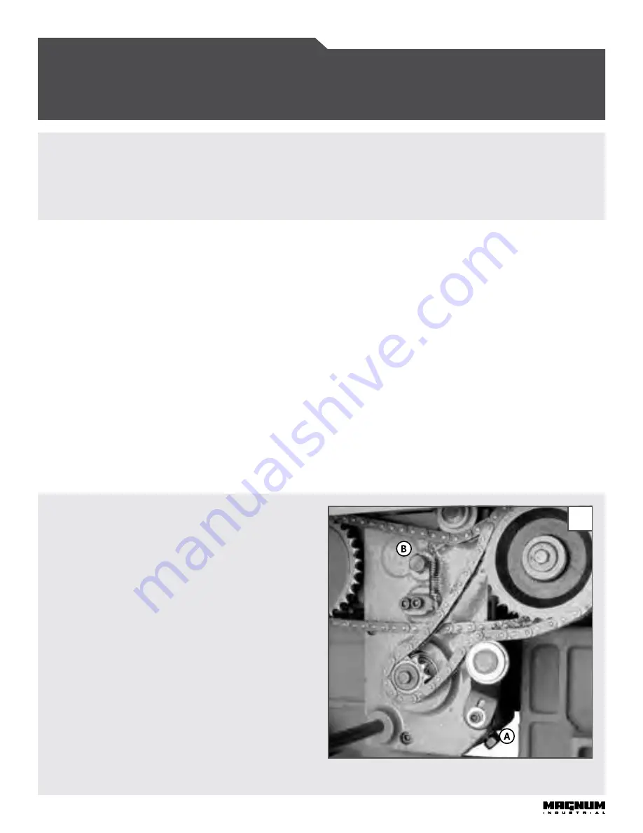
2.  Place a container under the 

DRAIN PLUG (A)

 and 

remove it using a 14 mm wrench. Once the gearbox 
is drained, reinstall the 

DRAIN PLUG (A)

, and then 

remove the 

FILL PLUG (B)

 using a 14 mm open wrench. 

See Figure 19.

3.  Fill the gearbox with a 80W-90 gear oil until it reaches 

the hole. Reinstall the 

FILL PLUG (B)

, and replace the 

panel, handwheel and feed speed adjustment knob.

FIGURE 19: CHANGING THE GEAR OIL

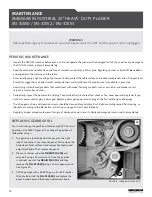
PERIODIC MAINTENANCE

•  Inspect the ON/OFF switches before each use. Do not operate the planer with a damaged switch. If you notice any damage to 

the ON/OFF switch, replace it immediately.

•  Keep the machine and table clean and free of sawdust, wood chips, pitch or glue. Regularly, vacuum or brush off loose debris 

and wipe down the machine and the table.

•  Occasionally apply a light coating of paste wax to help protect the table surface and reduce workpiece friction. Ask your local 

branch for suggestions on aftermarket surface cleaners and dry lubricants based on what is available in your area.

•  Avoid using silicon-based products that could react with wood-finishing products such as varnishes and lacquers or oil-, 

solvent- or water-based stains.

•  Periodically inspect the power cord and plug. To minimize the risk of electrical shock or fire, never operate the planer if you 

notice its power cord or plug is damaged. Replace a damaged power cord or plug at the first visible signs of damage.

•  The drive gears, chain and elevation screws should be cleaned of wood chips, dust, debris and old grease. After cleaning, re-

lubricate according to the lubrication instructions on page 11. Don't over lubricate. 

•  Regularly inspect planed workpieces for signs of damaged or worn inserts. Replace damaged or worn inserts immediately.

Содержание MI-31550

Страница 1: ...MODEL NO MI 31550 MI 31552 MI 31553 OPERATING MANUAL...

Страница 2: ...o minimize the risk of injury from kickback which occurs when the workpiece is ejected by the force of the cutterhead use proper feeding technique and stand to one side out of the path of a potential...

Страница 3: ...d electrician The machine must be connected to an electrical source using a power cord that has a grounding wire which must also be properly connected to the grounding prong on the plug The outlet mus...

Страница 4: ...ne is shipped from the factory partially assembled and requires only minimal assembly and set up before being put into service Before you assemble your band saw review the parts breakdown and keep it...

Страница 5: ...he corresponding holes in the machine Secure the chute with the six FLANGE BOLTS F Use a 10 mm wrench See Figure 6 CONNECTING TO A DUST COLLECTOR The dust chute connects to a 5 hose Make sure to use a...

Страница 6: ...ION The magnetic safety switch is equipped with an overload protection feature In the event of a spike in line voltage or amperage draw the internal overload protector will automatically trip and cut...

Страница 7: ...the height of the table rollers follow these steps 1 Loosen the LOCK LEVER B and turn the ADJUSTMENT LEVER C up or down as needed 2 Tighten the LOCK LEVER B to secure the rollers at the desired heigh...

Страница 8: ...rain in the wood Before being fed through the planer all lumber should be inspected for debris and foreign objects such as staples or nails Foreign objects embedded in your workpiece can be ejected fr...

Страница 9: ...appropriate feed speed for the stock use high speed for soft wood and slow for hardwood Experiment with feed speeds to find the right speed for each workpiece To increase the feed speed see Figure 14...

Страница 10: ...UT AND SCREW but do not tighten them yet 4 Center the INSERT HOLDER C with the flat edge of the NUT and fully tighten the NUT AND SCREW See Figure 17 5 Follow steps 1 to 4 with the remaining inserts T...

Страница 11: ...te the planer with a damaged switch If you notice any damage to the ON OFF switch replace it immediately Keep the machine and table clean and free of sawdust wood chips pitch or glue Regularly vacuum...

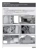
Страница 12: ...5 LUBRICATING ROLLER SPRINGS 25 LUBRICATION Lubricate the ELEVATION SCREWS A SLIDING SURFACES B and CHAINS C every month Use all purpose grease for the CHAINS and ELEVATION SCREWS Use all purpose oil...

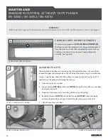
Страница 13: ...re located on the left side of the planer To access them remove the upper and lower panels on the left side of the planer using a 4 mm Allen key Using a straight edge check that the pulleys are proper...

Страница 14: ...and then raise or lower the two NUTS B with a 19 mm wrench to increase or decrease belt tension See Figure 30 2 Retighten the JAM NUTS A against the motor mounting plate 3 Close the motor access door...

Страница 15: ...rtation costs are not covered by the warranty As determined on a case by case basis parts may need to be inspected by an authorized Magnum Industrial representative before parts are eligible for warra...

Страница 16: ...43 1 43 2 43 3 43 4 43 5 43 6 PARTS LIST FOR MI 31550 MI 31552 MI 31553 43 1 6 7 2 3 4 5 1...

Страница 17: ...PARTS LIST FOR MI 31550 MI 31552 MI 31553...

Страница 18: ...PARTS LIST FOR MI 31550 MI 31552 MI 31553...

Страница 19: ...PARTS LIST FOR MI 31550 MI 31552 MI 31553...

Страница 20: ...5 23 2 0t 16 MI 31550 36 SCREW 4 MI 31550 37 LEFT SUPPORT SHAFT 1 MI 31550 38 HEX SCREW M8 1 25P 20 4 MI 31550 39 WASHER 1 MI 31550 40 CUTTERHEAD PULLEY 1 MI 31550 41 FLAT WASHER 6 2 22 3t 7 MI 31550...

Страница 21: ...5 FLAT WASHER 5 3 12 1 0t 4 MI 31550 96 ROUND HD SCREW M5 0 8P 16 4 MI 31550 97 STOP SWITCH 1 MI 31550 99 START SWITCH 1 MI 31550 100 HEX NUT M5 0 8P 8B 4H 2 MI 31550 101 SWITCH BOX 1 MI 31550 102 SOC...

Страница 22: ...LAT WASHER 13 5 28 2 0t 4 MI 31550 173 HEX SCREW M8 1 25P 25 6 MI 31550 174 SET SCREW M8 1 25P 20 6 MI 31550 175 DIGITAL READ OUT ASSY 9 inch 1 MI 31550 176 RELIEF BUSHING PGB21 16B 1 MI 31550 178 EXP...

Страница 23: ...24 WRENCH BOX 17 19 1 MI 31550 227 HEX SCREW M10 1 5P 35 14 MI 31550 231 FLAT WASHER 6 3 13 1 0t 4 MI 31550 232 CONNECT CORD MI 31550 MI 31552 MI 31553 SJT18AWG 3C 1750mm 1 MI 31550 233 KEY 6 6 40 1 M...

Отзывы: