
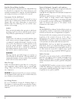
2. SPDT reed switch: Connect wiring to terminals per wiring
diagram in Figure 4. Connect wiring to flying leads per
wiring diagram in Figure 5.
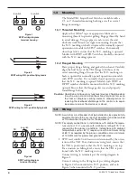
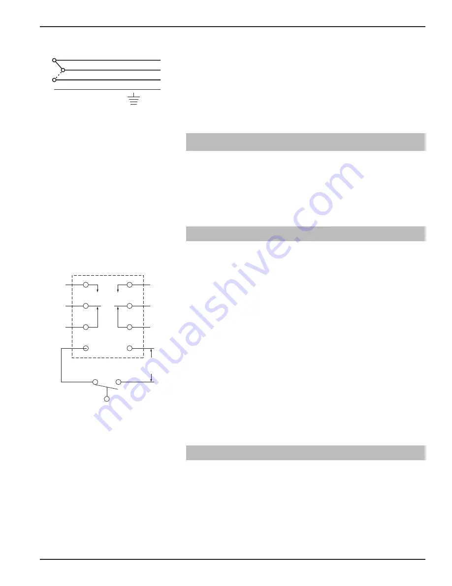
3. DPDT relay: Connect wiring to proper switch leads and
run power supply according to the wiring diagram. See
figure 6. This relay must be powered to function. 5A @
24 VDC relay requires 24 VDC power supply while the
5A @ 120 VAC relay requires 120 VAC power supply.
NOTE: Observe all applicable electrical codes and proper wiring
procedures.
2.0
Preventive Maintenance
Periodic inspections are a necessary means to keep your level
control in good working order. This control is a safety device
that protects the valuable equipment it serves. A systematic
program of preventive maintenance should be implemented
when the control is placed into service. If the following
instructions are observed, your control will provide reliable
protection of your equipment for many years.
2.1
Recommended Practice
2.1.1 Keep Control Clean
If applicable, be sure the switch housing cover is always in
place. This cover protects against damaging moisture and
acts as a safety feature by keeping bare wires and terminals
from being exposed. Should the housing cover become
damaged or misplaced, obtain a replacement immediately.
2.1.2 Inspect Connections Monthly
TK1 level switches may sometimes be exposed to excessive
heat or moisture. Under such conditions insulation on electri-
cal wires may become brittle, eventually breaking or peeling
away. The resulting bare wires can cause short circuits. Check
wiring carefully and replace at first sign of brittle insulation.
Check all electrical connections to ensure that they are tight.
Check wiring carefully and repair or replace if necessary.
2.1.3 Inspect Entire Model TK1 Unit Periodically
A periodic cleaning of the float, pivot and magnet assembly
will ensure continued free movement of the mechanism.
2.2
What to Avoid
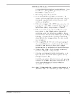
1. NEVER leave the switch housing cover off of the control
longer than is necessary to make routine inspections.
2. NEVER place a jumper wire across terminals to “cut-out”
the control. If a jumper is necessary for test purposes, ensure
that it is removed before placing the control into service.
3. NEVER use in systems containing iron particles. The magnet
in the float assembly can attract the particles and become
jammed.
4. NEVER put insulation over the switch housing.
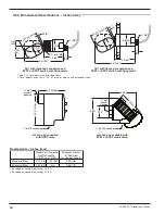
44-608 TK1 Liquid Level Switch
5
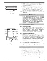
Figure 6
DPDT wiring diagram
BROWN
N.O.
GRAY
COM.
YELLOW
N.C.
BLUE
N.O.
WHITE
COM.
ORANGE
N.C.
RED
120 VAC or
24 VDC
LEVEL SWITCH
N.O.
RED
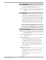
Figure 5
SPDT wiring for flying leads
Red NC
Orange NO
Green
Black C


