


5
WIRING (cont.)
SWITCH DIFFERENTIAL ADJUSTMENT
The standard differential of Series 75 level controls may be
field adjusted. Adjustment may be necessary if a wider
differential needs to be set to overcome switch chatter
caused by the process.
The differential, or the amount of level travel between
"switch-on” and "switch-off", may be adjusted by
repositioning the lower jam nuts on the float stem. This
adjustment is different for high level and low level
controls. Please refer to the appropriate section below for
adjustments instructions.
CAUTION:
Maximum differential adjustment is 25 mm (1”)
LOW LEVEL CONTROLS
On low level controls the switch trips on the lower actuation
point and resets on the higher actuation point. Widening
the differential will allow the switch to trip on the original
actuation point and reset at a later, or higher, point.
The differential on low level controls may be adjusted by
repositioning the lower jam nuts on the float stem. The
standard factory setting is for a minimum amount of play
(gap) between the top jam nuts and the attraction sleeve as
shown in Figure 6.
1.
Determine what change in differential is necessary.
NOTE: To widen the differential 25 mm (1"), the lower jam
nuts must be set proportionately lower on the stem [i.e. in
this example 25 mm (1")].
2.
Make sure power source is turned off.
3a. NEMA 4X/7/9 - Unscrew and remove switch housing
cover.
3b. CENELEC and BASEEFA - Loosen cover set screw,
unscrew and remove housing cover.
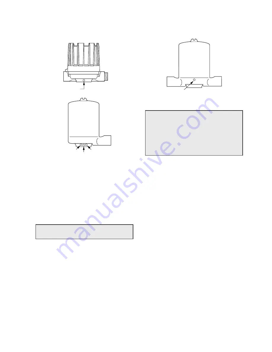
4. Disconnect power supply wires from switch mecha-
nism. Pull wires out of conduit connection opening in
housing base. See Figure 5.
5. Perform system shut-down procedures as required to
relieve pressure from float chamber of control. Allow
unit to cool.
a. Close shut-off valves (if so equipped) to isolate
control from tank. Drain off liquid in float chamber.
See Figure 3 on page 4.
b. On installations without shut-off valves, relieve
pressure from the tank. Drain liquid in tank to a level
below the connections of the float chamber.
NOTE: Level control, connections and pipe lines need not
be removed from the tank.
6.
Loosen enclosing tube nut with a 35 mm wrench.
Unscrew enclosing tube counterclockwise (switch
and housing base will rotate also), until it is free.
See Figure 5.
7.
Lift enclosing tube, switch, and base off float chamber.
Jam nuts and attraction sleeve are now accessible.
8. Measure the distance “D” from the top edge of the
upper jam nuts to the top of the float stem. See Figure
7. Record this measurement.
9. Loosen and remove upper jam nuts, guide washer and
attraction sleeve.
10. Loosen and adjust lower jam nuts to the desired
position. Tighten lower jam nuts securely. See Figure
7.
11. Replace attraction sleeve on stem.
12. Replace upper jam nuts and guide washer on the stem
in the position previously noted. Tighten upper jam
nuts securely. See Figure 7.
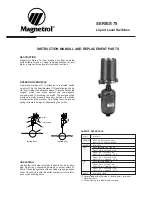
Set screw
Set screw
Locking screw
Set screw
Position
screw
CAUTION:
- DO NOT attempt to reposition NEMA 4 /
NEMA 7/9 housings without loosening the
set screws; CENELEC/BASEEFA housings
MAY NOT BE REPOSITIONNED. ALWAYS
retighten set screw(s) after repositionning.
- DO NOT attempt to unscrew cover of CEN-
ELEC/BASEEFA housings before loosening
locking screw in base of housing. ALWAYS
retighten locking screw after replacing cover.
Figure 4c
Figure 4a
Figure 4b
NEMA 4x
NEMA 7/9
CENELEC/BASEEFA
OBSERVE ALL APPLICABLE ELECTRICAL CODES AND PROPER WIRING PROCEDURES
Содержание 075
Страница 13: ...13 ...


