

36054 MONTEBELLO VICENTINO (VI) Italy
Via Fracanzana, 14
Tel. (+39) 0444 649399 - Fax (+39) 0444 440495
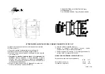
INSTRUCTIONS FOR THE INSTALLATION OF “BR” TACHOGENERATOR
a) Comply strictly with the measurements on the above drawing.
b) Pull out the rotor (1).
c) Remove the white plastic commutator cover cap (2).
d) Oil the shaft and assemble the rotor.
e) Fix the rotor by tightening the fixing ring using the corresponding
allen screw (3).
f)
Refit the white plastic commutator protection cap (2).
This
operation is very important since otherwise
there is liklihood of
damaging
the commutator with the resulting increase in wear on
the brushes and poor functioning of the tachogenerator.
g) Fit the case cover securing (4) it to the motor casing by means of 2
galvanised screws M5x55 (5).
h) Pull out the white plastic cap (2).
i) Insert the brushes in the appropriate housing: fully tighten the 4
plastic caps.
j) Fix the covering cap (7) with the corresponding seal (6) by means of
3 hexagonal screws M5x8 (8,9).
MARKING OF TERMINALS IN ACCORDING TO IEC 34-8
Counter clockwise rotation looking from coupling side
BRB BR
Terminal A1: positive (+)
green blue
Terminal A2. negative (-) red black