Interconnections
31
Terminal
Description
Incremental Encoder
Connections
HPV900
Series
2
HPV900
HPV600
option
card
A
TB1-1
TB1-21
TB2-63
/A
TB1-2
TB1-20
TB2-62
B
TB1-3
TB1-23
TB2-65
/B
TB1-4
TB1-22
TB2-64
Z
TB1-19
N/A
N/A
/Z
TB1-20
N/A
N/A
e5
/+12VDC
TB1-17
TB1-25
TB1-24
TB2-67
TB2-66
encoder
common
TB1-18
TB1-19
TB2-61
Shield
TB1-5
TB1-26
TB2-68
Table 6: Encoder Connections
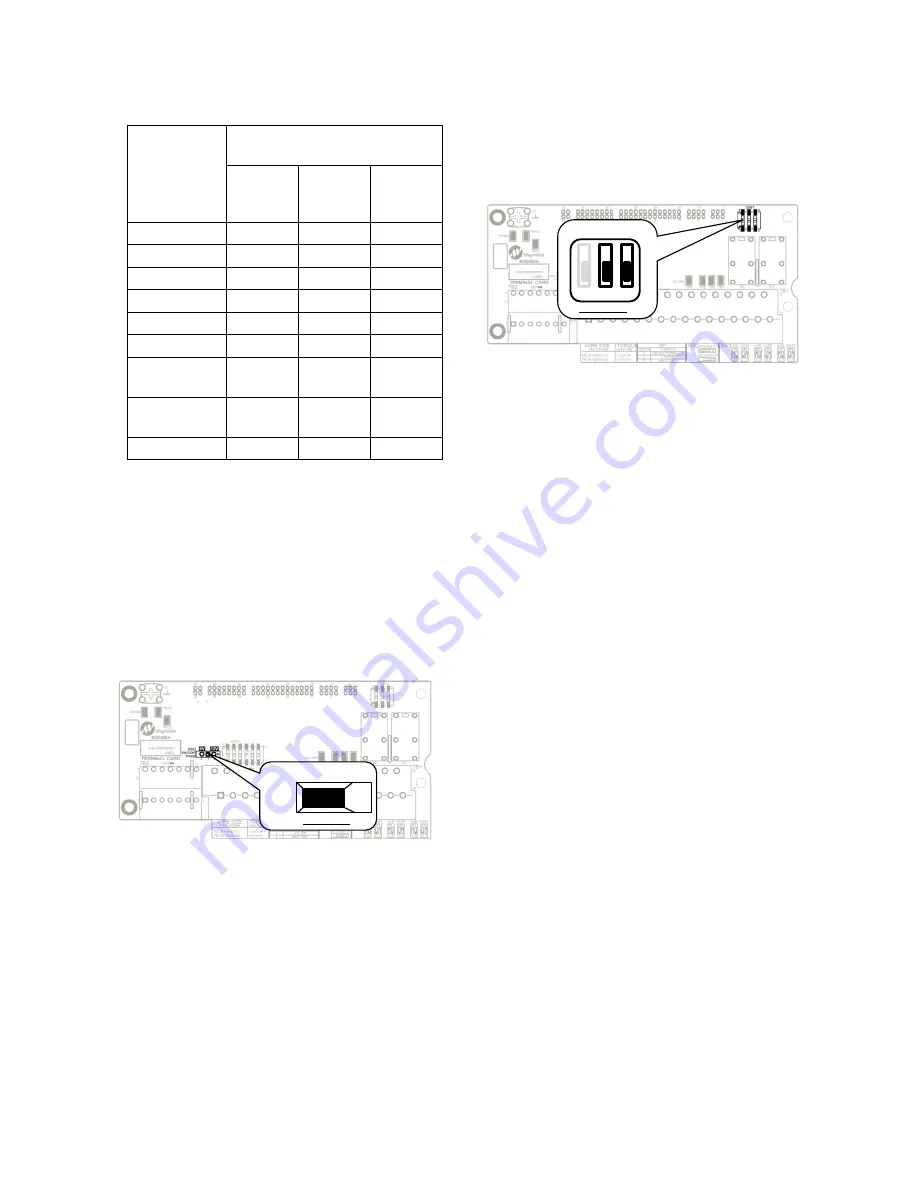
Incremental encoder Voltage Selection
The HPV 900 Series 2 drive allows for either
an is5VDC power supply or an isolated
+12VDC power supply. The drive is defaulted
with the +5VDC power supply. If the +12VDC
power supply is desired, change the SW2
switch as seen in the figure below from +5V
position to the +12V position
Figure 19: TerMag Board Encoder Voltage
Selection
EnDat Encoder Connections
The HPV 900 PM has an absolute encoder
option card that reads absolute rotor position
data and converts analog incremental
(sine/cosine) signals into standard quadrature
feedback signals. The drive’s encoder circuitry
incorporates resolution multiplication (8x). The
output quadrature signals are available for use
by the car controller.
NOTE:
If a EnDat board is installed in the drive
with a TerMag board with a part number
46S04284-1020, the A/B and Z filters on SW1
on the TerMag board should be turned off
(SW1-2 and SW1-3 in down position).
Figure 20: TerMag Board Encoder Filters
Encoder Wiring
Use twisted pair shielded cable with shield tied
to chassis ground at drive end using the
ground clamp provided, in order to minimize
magnetic and electrostatic pick-up current and
to minimize radiated and conducted noise.
Reasonable care must be taken when
connecting and routing power and signal
wiring. Radiated noise from nearby relays
(relay coils should have R/C suppressors),
transformers, other electronic drives, etc. may
be induced into the signal lines causing
undesired signal pulses.
Power leads and signal lines must be routed
separately. Signal lines should be shielded
and routed in separate conduits or harnesses
spaced at least 12 inches apart from power
wiring. This protects the cable from physical
damage while providing a degree of electrical
isolation. Also, do not run cable in close
proximity to other conductors, which carry
current to heavy loads such as motors, motor
starters, contactors, or solenoids. Doing so
could result in electrical transients in the
encoder cable, which can cause undesired
signal pulses. Power leads are defined as the
transformer primary and secondary leads,
motor leads and any 120 VAC or above control
wiring for relays, fans, thermal protectors, etc.
HPV 900 S2 PM EnDat Encoder
Magnetek recommends using a 17-pin circular
(M23) flange socket paired with a Heidenhain
309778-xx cable. Also acceptable are:
encoder pigtail cable up to 1m in length fitted
with M23 (17-pin male) coupling (291698-25,
291698-26, or 291698-27) and paired with a
5V
12V
default:5V
SW2
default: off
1
2
3
on
off
SW1
Содержание HPV 900 Series 2
Страница 4: ......
Страница 195: ...APPENDIX Dimensions Mounting Holes Weights 173 Figure 46 Frame 2 Dimensions Mounting Holes and Weight...
Страница 196: ...APPENDIX Dimensions Mounting Holes Weights 174 Figure 47 Frame 3 Dimensions Mounting Holes and Weight...
Страница 197: ...APPENDIX Dimensions Mounting Holes Weights 175 Figure 48 Frame 3 5 Dimensions Mounting Holes and Weight...
Страница 198: ...APPENDIX Dimensions Mounting Holes Weights 176 Figure 49 Frame 4 Dimensions Mounting Holes and Weight...
Страница 199: ...APPENDIX Dimensions Mounting Holes Weights 177 Figure 50 Frame 5 Dimensions Mounting Holes and Weight...
Страница 227: ...205 Z Z MARKER LOST 150 Zero Speed Level parameter 47 Zero Speed logic output 105 Zero Speed Time parameter 47...
Страница 228: ......
Страница 229: ......


