Gauss-/Teslameter
FH 52
BA - Nr.: 1620010102
Page 30
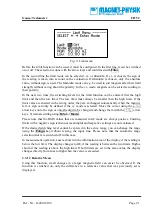
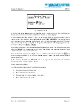
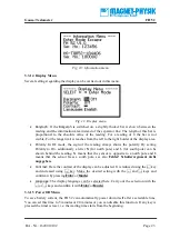
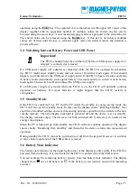
B
v
F
L
B
U
H
d
I
+
-
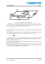
Fig. 17: Operating principle of a Hall generator
A control current
I
is flowing through the Hall generator. When this is exposed to a magnetic
flux density
B
that is directed perpendicular to the surface of the sensor element, a force known
as the Lorentz force acts on the moving electric charge carriers,
)
(
B
v
q
F
L
=
,
where
v
is the drift speed of the charge carriers,
q
their charge and
B
the flux density of the
magnetic field.
The Lorentz force diverts the charge carriers to the side surface of the Hall generator so that an
electric voltage, the Hall voltage
U
H
, can be measured between the opposite sides,
d
B
I
R
U
H
=
H
.
The Hall voltage is thus in the first approximation proportional to the flux density. The Hall
constant
R
H
depends on material parameters and therefore also on the temperature and to a
small extent on the flux density
B
.
The simplest method to keep the resulting linearity error as small as possible is loading the Hall
voltage with an appropriate resistor.
High quality instruments, as the FH 52, additionally carry out a computed correction for the
non-linearity. Therefore the characteristic curve of the sensor is measured. The points are stored
in a data memory that is integrated in the plug of the probe.


