Assembly the two wooden bases to the bottom of unit by the supplied assembly screws and screwdriver as the figure above.
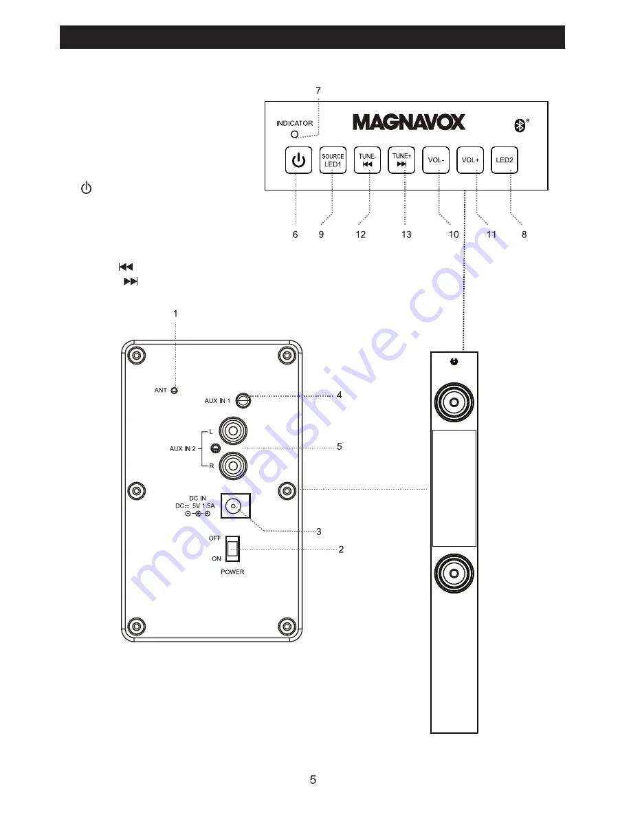
LOCATION OF CONTROLS
1. ANT (FM Antenna)
2. POWER ON/OFF Switch
3. DC IN Jack
4. AUX IN 1 Jack
5. AUX IN 2 Jacks
6. (Standby On/Off) Button
7. Indicators
8. LED 2 Button
9. SOURCE/LED 1 Button
10. VOL - (Volume Down) Button
11. VOL + (Volume Up) Button
12. TUNE-/ Button
13. TUNE+/ Button
Top View:
Rear View:


