50
5�2 LED Lights
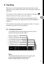
The LED indicators on the Askis PSI-15 and Askis PSI-20 models
indicate the status of the device.
LED Signal
Bedeutung
A
Green „
Power“, permanent
The battery is connected and the
device has been switched on.
The inverter is ready for operation
B
Red „
Error“, permanent
There is an error – please try to
solve the problem using chapter 7
„Troubleshooting“
B
Red „
Error“, flashing
There is an error – please try to solve
the problem using chapter 7 „Trouble-
shooting“
5�3 USB output
5 V consumers up to 2.1 A can be directly connected to the
USB output.
5�4 Fan
The fan is load and temperature controlled.
The fan starts automatically when a certain load or internal
temperature is reached.
6 Safety Devices
6�1 Undervoltage protection
If the input voltage (on the battery side) is too low, the device
emits a loud acoustic signal (beep).
Signal is
activated:
lower 10.5 V DC (± 0.5 V)
Signal is
deactivated:
above 11.5 V DC (± 0.2 V)
Содержание ASKIS PSI-10
Страница 2: ...2...
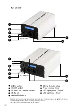
Страница 15: ...DE 15 R ckseite 8 9 10 8 9 10 Roter Anschluss Schwarzer Anschluss L fter 8 9 10...
Страница 30: ...30...
Страница 31: ...EN 31 Pure Sine Inverter PSI 6 PSI 10 PSI 15 PSI 20 12 V 230 V Assembly and Operating Instructions...
Страница 43: ...EN 43 Backside 8 9 10 8 9 10 Red connector Black connector Fan 8 9 10...

