background image

Page 9 

2.1.4. Lighting Procedure (Optimum Control and Trim Switch Control)

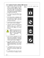
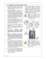
1.  Ensure the main burner is off by pressing 

the button on the trim marked 


(‘small flame/dot’) until clicking is heard 
on the valve (see 

Figure 12

/

Figure 13

). 

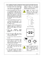
2.  With the gas available at the valve press 

in the IGNITION KNOB and turn it 
anticlockwise to the pilot flame position 
(see 

Figure 14

)

.  

A click of the piezo 

igniter will be heard and a spark will 
appear at the electrode.  At the same 
time the gas will flow to the pilot burner 
and will be ignited by the spark.  Repeat 
the procedure until the pilot flame is 
established. 

3.  Keep the knob pressed in for a further 10 

- 12 seconds and slowly release.  The 
pilot flame should stay alight.  If the 
flame goes out repeat procedure above 
to establish the pilot. 

4.  If the spark unit fails to light the pilot, the 

appliance may be lit manually by 
applying a lighted match or taper to the 
pilot jet and following the above 
procedure. 

5. 

Turn the IGNITION KNOB 
anticlockwise to the main flame 
position.


6.  Press and hold the 

 (‘large flame’) 

button (in 

Figure 12

/

Figure 13

) until 

clicking is heard (fully open). 

7.  The main burner will have cross-lit from 

the pilot. 

8.  Now the gas rate can be adjusted to the 

desired setting by pressing the 


(‘small flame/dot’) button.  Any rate 
between the pre-set high and low can be 
obtained using the two buttons. 

9.  To switch off the main burner press and 

hold the 

 (‘small flame/dot’) button 

until clicking is heard from the valve 
(OFF position).   

10. The fire can safely be left in this position 

at all times, however to prevent 
unauthorised or accidental use (say by 
children) it is recommended to turn the 

IGNITION KNOB to the pilot flame 
position by turning it 90 degrees 
clockwise.  To turn the pilot off, turn the 
IGNITION KNOB fully clockwise. 


NOTE:

 The clicking sound 

made by the valve is the 
operation of the valve clutch, 
and indicates either maximum 
or minimum positions.


TRIM

HIGH

LOW
OFF

/


Figure 12 – Trim Switch 


Figure 13 - Wall Switch 

IGNITION

KNOB

GAS RATE

ADJUSTING

KNOB

GAS VALVE


Figure 14 


NOTE:

 No attempt should be 

made to relight the fire for at 
least 3 minutes after the pilot 
flame has been extinguished 
either intentionally or 
unintentionally.


Содержание DUO

Страница 1: ...G LPG Control Options Manual BM Control Upgradeable Manual Control Remote Control Response S Optimum Control Trim Switch Control Total Control Installation Options Installation using Freedom Surround...

Страница 2: ...ithin one year of purchase Burley Magiglo will arrange to repair or replace the item free of charge Any claims under this warranty must be made through the retailer from whom the product was purchased...

Страница 3: ...ing the Fire Bed and the Imitation Coals Pebbles 19 2 9 2 Cleaning the Pilot 20 2 9 3 Cleaning the Fire Back 20 2 9 4 Black Painted Metal Surfaces 20 2 9 5 Brass or Chrome Surfaces 21 2 9 6 Stainless...

Страница 4: ...uctions 41 4 3 Replacing Parts 42 4 3 1 Pilot Assembly Replacement 42 4 3 2 Injector Replacement 42 4 3 3 Control Valve Replacement BM and Mertik GV34 42 4 3 4 Motor Replacement Remote Control Optimum...

Страница 5: ...in GB should follow the recommendations of the following current British Standards BS 5871 Pt 3 Installation of Decorative Fuel Effect Gas Fires BS 6891 Pipe work Installation BS 5440 Pts 1 2 Flues a...

Страница 6: ...ease refer to the full Flue and Chimney Requirements within the Installation Instruction section Gas Supply 1 This range of decorative gas fires are suitable for use with either Natural Gas G20 at 20m...

Страница 7: ...inimum of 5 square inches of free air space below the base of the fire Minimum opening free air in fire fret Minimum opening free air in ash pan cover Figure 1 Fire Front Specification Height to Centr...

Страница 8: ...Page 4 This page is left intentionally blank...

Страница 9: ...appropriate operating instructions in the appropriate section Control Valve Operation Control Type Manual Manual BM Control See Section 2 1 1 on Page 6 Manual Upgradeable Manual Control See Section 2...

Страница 10: ...anually by applying a lighted match or taper to the pilot jet and following the above procedure NOTE No attempt should be made to relight the fire for at least 3 minutes after the pilot flame has been...

Страница 11: ...8 4 Turn the GAS RATE ADJUSTING KNOB fully anticlockwise until you reach the stop position i e the maximum gas rate See Figure 9 5 The main burner will have cross lit from the pilot 6 Now the gas rate...

Страница 12: ...his process the main burner will ignite from the pilot 7 By pressing the two buttons together to increase the gas rate and the lower button only to decrease the gas rate the valve can be manipulated t...

Страница 13: ...main flame position 6 Press and hold the large flame button in Figure 12 Figure 13 until clicking is heard fully open 7 The main burner will have cross lit from the pilot 8 Now the gas rate can be adj...

Страница 14: ...s the large flame to increase the flame height or small flame to decrease the flame height on the handset see Figure 16 5 For fine adjustment tap the or buttons 6 To leave the burner in the standby mo...

Страница 15: ...further 10 seconds and slowly release The pilot should stay alight Repeat step 4 if necessary 6 Turn Manual knob anticlockwise to ON position 7 Turn the Gas Rate adjusting knob anticlockwise to ON pos...

Страница 16: ...ceiver Unit 1 Remove the receiver unit from under the fire burner or from wherever positioned if mounted remotely and remove the battery compartment cover see diagram 2 Replace the old batteries with...

Страница 17: ...t way up 5 Secure with screws REAR OF WALL PLATE CABLE TO VALVE BATTERY PACK 4 x 1 5 V AA BATTERIES LOW OFF SWITCH HIGH SWITCH brown brown brown blue blue blue white black Figure 21 2 4 Battery Replac...

Страница 18: ...vicing we recommend that you use a HEPA filtered vacuum to remove any dust and soot accumulated in and around the fire before and after working on the fire to ensure that the release of fibres from th...

Страница 19: ...ly together will result in a poor flame picture The best results come from a loose fuel build 5 Do not place any coals immediately over the pilot assembly 6 After the appliance has been allowed to war...

Страница 20: ...ith the legs facing up ensuring that none of the port holes are blocked 2 Place pebbles C D in position as shown in Figure 27 3 Place pebbles A B C in position as shown in Figure 28 4 Place pebbles A...

Страница 21: ...ralise the trim as necessary Magnets Figure 31 2 7 Fitting an ioss Fascia if supplied 1 The Fascia is coated with a protective film This must be removed by peeling off before fitting the fascia 2 The...

Страница 22: ...erally heating appliances will create warm air convection currents that will transfer heat to any wall surface against which they are located Some soft furnishings including blown vinyl wallpapers may...

Страница 23: ...ory Ceramic Fibres RCF we recommend that the replaced items are not broken up but are sealed within heavy duty polythene bags and clearly labelled as RCF waste RCF waste may be disposed of in suitably...

Страница 24: ...pair of tweezers if available or a piece of fine soft wire pick out the lint from the lint guard 2 With the aid of a small nozzle attachment on your vacuum cleaner apply suction at the lint guard on t...

Страница 25: ...removed the surface can then be re polished using 3M Scotchbrite pads Fine Grade Periodically it may be necessary to coat the entire surface in order to achieve a uniform finish This can be achieved...

Страница 26: ...Page 22 This page is left intentionally blank...

Страница 27: ...3 The flue should be sound free from obstructions and if it has previously been used with a solid fuel or oil fired appliance it should be swept before installing this gas fire The flue must be inspe...

Страница 28: ...und Hearth Figure 35 Pre Cast Flue to BS EN 1858 Fire Surround Hearth 100mm 125mm 575mm Twin Wall Metal Flue Flue Box Figure 36 BS 715 Flue Box Fireplace Opening Size mm Applies to all cases Min Max H...

Страница 29: ...ed previously for an oil or solid fuel appliance 270mm 195mm 270mm 195mm 195mm 265mm Table 2 Debris Collection Area For Trim Switch Models the above dimensions can be reduced by 15mm 3 3 General Dimen...

Страница 30: ...Approved Document J paragraph 3 40 currently states Appliance should be placed on hearths unless a they are installed so that every part of any flame or incandescent material will be at least 225mm ab...

Страница 31: ...or incandescent material Table 4 Models with Freedom Surround OH 680mm OW 565mm OD 195mm HW Refer to Appliance Location details on Page 26 HD Refer to Appliance Location details on Page 26 Table 5 Ot...

Страница 32: ...unted decorative bar etc All Duo Models W Must project a minimum of 150mm either side of any naked flame or incandescent material D Must project a minimum of 300mm in front of any naked flame or incan...

Страница 33: ...le of physical barrier dimensions as stated in Table 6 Protected Area D W Figure 47 Example of physical barrier dimensions as stated in Table 6 Protected Area D W 50mm Min Figure 48 Example of physica...

Страница 34: ...ing the fire in Northern Ireland NI purpose provided ventilation must be provided in accordance with the rules in force In other EC countries equivalent rules in force must be used 3 6 Technical Data...

Страница 35: ...surround 30mm spacer if specified 1 Isolation valve Additional Items for Remote Control Models and Total Control Models Quantity Item 1 Remote Control Handset and Receiver 4 AA Batteries 1 PP3 9V Bat...

Страница 36: ...sections 3 3 3 4 and 3 6 3 9 1 Installation using Freedom Surround The Freedom Surround is designed to provide an alternative installation method giving it a contemporary hole in the wall appearance...

Страница 37: ...5 Place the Freedom Surround into the prepared opening threading the cables through the vine eyes and through the holes in the base of the surround as shown in Figure 54 6 Tighten the cables using th...

Страница 38: ...hrough leaving the remaining two intact 5 Place the box centrally within the fireplace opening and push it back until the sealing foam abuts the face of the fire surround 6 Mark the box fixing holes l...

Страница 39: ...arefully place the burner tray in the firebox ensuring that the bracket at the rear of the tray engages into the slot at the back of the box and secure the tray to the box with the previously removed...

Страница 40: ...ose in Sections 3 9 7 to 3 9 10 as applicable 3 9 7 Continuation of Installation Remote Control Model 1 Unpack the box containing the Receiver and the Hand Set 2 Fit four AA 1 5V batteries into the re...

Страница 41: ...ring correct polarity The cable connectors must be matched to the appropriately sized spade connector Also ensure that the cable is neatly tucked away and not touching the underside of the tray 5 Fit...

Страница 42: ...trol on page 9 4 Proceed to Section 3 9 11 to commission the appliance 4xAA BATTERIES Figure 61 3 9 10 Continuation of Installation Total Control 1 Unpack the box containing the receiver and hand set...

Страница 43: ...information is given on the data badge of the appliance 6 If the correct pressure cannot be achieved then some potential causes of low pressure are a Supply pipes are not of large enough diameter b Th...

Страница 44: ...lt Disconnect the fire and seek expert advice The imitation fuels must be laid in accordance with the instructions prior to commencing the spillage test smoke match applied 6 12mm inside opening Figur...

Страница 45: ...that the gas and electrical supply where applicable have been isolated After any servicing or replacement of any parts the appliance should be re commissioned 4 2 Servicing Instructions As part of th...

Страница 46: ...y 6 Refit in reverse order ensuring that the lint guard is fitted 4 3 2 Injector Replacement 1 Undo the two compression nuts on the gas feed pipe to the injector elbow and remove the pipe 2 Loosen the...

Страница 47: ...over 6 Turn the gas rate adjusting knob fully anticlockwise and gently manipulate the motor free from the valve see note See Figure 67 and Figure 68 7 Replace with new motor ensuring that the motor is...

Страница 48: ...out the receiver from under the heat shield and remove the batteries 2 Gently pull out the HT lead and the valve cable from the receiver see Figure 70 3 Unscrew and remove the SW and TC connections 4...

Страница 49: ...eased a Loose thermocouple connection at control valve end Remake thermocouple ensuring the connection is firm b Faulty Thermocouple Replace complete pilot assembly Pilot and main burner go out when c...

Страница 50: ...l 4 AA batteries Remote Control will turn fire off but will not turn on Incorrect hand set operation Ensure two buttons are pressed to turn on A prolonged audible signal is heard when attempting to li...

Страница 51: ...Page 47 This page is left intentionally blank...

Страница 52: ...tents 2193802 2240620 and 2256920 Other Patents Pending Magiglo is a registered trademark of Burley Appliances Ltd Burley Appliances Ltd Lands End Way Oakham Rutland LE15 6RB Tel 01572 725570 Fax 0157...

Отзывы: