


508196-01
Issue 2120
Page 9 of 18
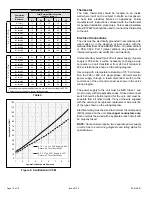
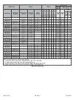
Model Number
Filter Area
(in
2
)
*MHP4-12-09*
*MHP4-12-12*
265
3MHP4-12-18*
5MHP4-12-18*
310
7MHP4-12-18*
10MHP4-12-18*
360
*MHP4-12-24*
400
*MHP4-12-30*
515
*MHP4-14-36*
600
Table 5. Minimum Required Surface Area for
Disposable Filters
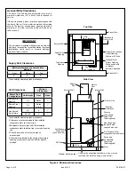
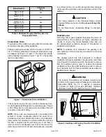
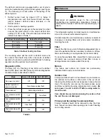
Condensate Drain
Provisions must be made to properly drain the primary and
secondary drain pans of this appliance.
Primary drain and secondary drain connection: 3/4” NPT to
3/4” PVC fitting (schedule 40 minimum). Both drains must
be trapped as shown in Figure 7. The drain line should
pitch gradually downward at least 1” per 10’ of horizontal
run to an open drain.
Figure 7. Condensate Drain Installation
If local codes require the use of metal condensate lines,
do not thread metal fittings into the unit drain pans. Thread
a PVC fitting into the unit drain pans and make the field
connection to the PVC fitting.
NOTE:
These units are designed with a redundant drain
system to handle condensate without the need for an
emergency drain pan. Should the indoor coil condensate
drain system fail, all water is contained within the unit and
the flow is directed into the unit base pan. From there it
will drain into the condensate riser. If for some reason the
water cannot drain into the main condensate riser, all water
is contained in the unit, and the design will allow drainage
out through the wall sleeve and louver to the outside of the
building.
Use thread sealant on the threaded fittings. Install
threaded fittings by hand only.
Do not over torque the
fittings.
Do not thread metal condensate fittings to unit drain
pans.
CAUTION
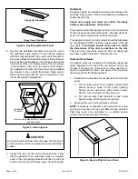
Ventilation Air
Units ship with a panel installed that seals the return air
compartment at the ventilation air intake. Installers can
choose to remove the factory-installed panel and use
the field-provided ventilation damper if introduction of
ventilation air is desired.
NOTE:
If ventilation air is introduced, the quantity of air
and conditions of this air must be accounted for in the load
calculations.
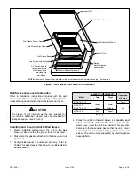
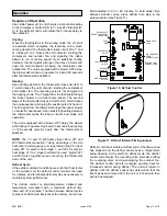
The auxiliary panel has nine knockouts to configure
ventilation air flow to installation requirements. Use Table
6 and Figure 8 to determine which knockouts to remove
from the auxiliary panel in order to achieve the desired
ventilation air flow. Use a flat head screw driver to remove
the knockouts. Set the factory-installed panel aside for
possible future changes.
The location of ventilation air capable models must
conform to the requirements of National Fire Protection
Association NFPA No. 54 in regards to proximity
of forced air inlets to flue gas terminals. Improper
installation could result in personal injury or death.
WARNING
Figure 8. Auxiliary and Factory Panel for Ventilation
Air
Factory panel
Ventilation
Air Duct
Auxillary panel
with knockouts
1
2
3
4
5
6
7
8
9