background image


Page 6 

INDEX 

1 INTRODUCTION ………………………………………………………………………….  

1.1 Definition of the operator …………………………………………………………………………………  
1.1.1 Operator’s requirements ……………………………………………………………………………….   
1.1.2 Operator’s prohibitions …………………………………………………………………………………   
1.2 Operator’s obligations ……………………………………………………………………………………    
1.3 Importance of the manual ………………………………………………………………………………..  
1.4 Regulatory references …………………………………………………………………………………….  
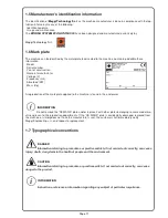
1.5 Manufacturer’s identification information ……………………………………………………………….  
1.6 Mark plate ……………………………………………………………………………………….   
1.7 Typographical conventions ………………………………………………………………………………..  
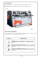
1.8 Conventions …………………………………………………………………………………………………    
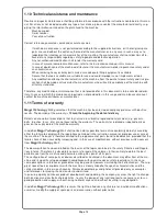
1.9 Personnel qualifications …………………………………………………………………………………... 
1.10 Technical assistance and maintenance …………………………………………………………….   
1.11 Terms of warranty …………………………………………………………………………………….   

2 GENERAL WARNINGS ……………………..…………………………………………..   

2.1 Safety regulations …………………………………………………………………………………………   
2.2 Safety warnings for maintenance …………………………………………………………..   
2.3 Signs of danger …………………………………………………………………………………………   
2.4 General prohibition signs ………………………………………………………………………………..   
2.5 Obligation signs ………………………………………………………………………………………..   
2.6 Signs affixed to the machine  ……………………………………………………………………..   

3 MACHINE’S DESCRIPTION ……………………………………………………………. 

3.1 Machine’s description …………………………………………………………………………………….. 
3.2 Machine’s composition …………………………………………………………………………… 
3.3 Axes ……………………………………………………………………………………………... 
3.4 Axes’ description …………………………………………………………………………………………… 
3.5 Job specification ………………………………………………………………………………. 
3.6 Machine’s dimension ……………………………………………………………………………………... 
3.7 Machine’s characteristic …………………………………………………………………………………... 
3.8 Technical characteristic …………………………………………………………………………………. 
3.9 Noise level ……………………………………………………………………………………... 
3.10 Dust emission …………………………………………………………………………………………. 

4 TRANSPORT AND INSTALLATION …………………………………………... 

4.1 Condition for standard use of machine ..……………………...………………………………………… 
4.1.1 Standard conditions ..……………………………………………………………………………………. 
4.1.2 Temperature .……………………………………………………………………………………………... 
4.1.3 Atmospheric condition …………………………………………………………………………………... 
4.1.4 Lighting …….……………………………………………………………………………………………... 
4.2 Working area ………………………...……………………………………………………………………. 
4.3 Lifting and transport …….…………………………………………………………………………………. 
4.3.1 General information ..……………………………………………………………………………………. 
4.3.2 Personnel’s qualification ………………………………………………………………………………... 
4.3.3 Lifting instruction ………………..……………………………………………………………………….. 
4.3.4 Condition for the machine’s safeguard ………...……………………………………………………… 
4.3.5 Control for possible damages …..……………………………………………………………………… 
4.4 Preparation of the installation area …...………………………………………………………………….. 
4.4.1 Installation requirements ...……………………………………………………………………………… 
4.4.2 Machine’s positioning …………..……………………………………………………………………….. 
4.5 Assembling .………………………………………………………………………………………………… 
4.6 Electrical connection ...…………………………………………………………………………………….. 
4.6.1 Electrical system feature ……..…………………………………………………………………………. 
4.6.2 Ground phase connection ...…………………………………………………………………………….. 
4.7 Pneumatic connection …...………………………………………………………………………………… 
4.8 Suction connection ………………………………………………………………………………………… 

5 COMMAND - SOFTWARE ……………..……………………………………………….. 

5.1.1 Command console ……………………………….……………………………………………………… 
5.1.2 Commands main menu ………..………………………………………………………………………... 
5.1.2.1 Machine Data Editor …………………………………………………………………………………. 
5.1.2.2 CAD 4 ……………...………………………………………………………………………….. 
5.1.2.3 Job List ……………………………………………………………………………………………….. 
5.1.2.4 Single program ..…..….……………………..……………………………………………………. 
5.1.2.5 Ant.-Post upload-download……………………………………………………………………………. 
5.1.2.6 Mirror process ……….…...……………………………………………………………………………. 
5.1.2.7 “Ribattuta” process…………………………………………………………………………………… 
 

08 
08 
09 

08 

08 

11 
11 

10 

10 

11 

12 
12 
13 
13 
14 
14 
14 
15 
15 
16 
16 
16 
16 
19 
22 
22 
26 
27 
27 
27 
28 
28 
28 
28 
28 
28 
28 
28 
29 
29 
29 
29 
29 
30 
30 
30 
30 
31 
32 
32 
32 
33 
33 
34 
34 
34 
35 
36 
39 
51 
56 
57 
58 
58 

Содержание EVOLUTION 1000

Страница 1: ...ge BORING SYSTEM EVOLUTION 1000 UK MACHINE CODE 17824101 MANUAL CODE 00008027 EDITION 07 2014 ORIGINAL USE AND MAINTENANCE MANUAL ALWAYS KEEP THIS MANUAL TOGETHER WITH THE MACHINE WOODWORKING MACHINER...

Страница 2: ...Page 2 Page intentionally left blank...

Страница 3: ...ertaldo FI ITALY Declares that the machinery complies with all relevant provisions of the directive 2006 42 EC Machine 2004 108 EC EMC and compile the technical file of the above machinery Adesivo tar...

Страница 4: ...Page 4 Page intentionally left blank...

Страница 5: ...this manual is on full responsibility of the user The manufacturer does not grant any further guarantee for any imperfections incompleteness and or operating difficulties expressly excluding any resp...

Страница 6: ...ANSPORT AND INSTALLATION 4 1 Condition for standard use of machine 4 1 1 Standard conditions 4 1 2 Temperature 4 1 3 Atmospheric condition 4 1 4 Lighting 4 2 Working area 4 3 Lifting and transport 4 3...

Страница 7: ...s specific and difficult area 6 MAINTEINANCE 6 1 1 Warning for manteinance 6 1 2 Operation with specific technicalskills 6 1 3 Cleaning 6 1 4 Periodical control 6 1 5 Condensate descharge 6 1 6 Air pr...

Страница 8: ...idents at work It is deemed of fundamental importance to underline that the operator who is not in perfect psychophysi cal faculties condition can cause serious harm to himself others animals or prope...

Страница 9: ...a serious and immediate danger to safety and health and of any shortcomings in the protection arrangements cooperate in accordance with national practice with the employer and or workers with specifi...

Страница 10: ...November 1996 Implementation of Directive 93 68 CEE on CE marking of electrical equipment Legislative Decree no 615 of 2nd November 1996 Implementation of Council Directive 89 336 EEC of 3 May1989 on...

Страница 11: ...pplied to the machine is found in the enclosures Do not remove the CE MARK plate and or replace it with other plates belonging to same model ma chines present in the production departments If the CE M...

Страница 12: ...o read or understand the following classification is defined FRONT BACK SYMBOL IDENTIFICATION OPERATOR Qualified and authorised person in charge of running the ma chine with working guards and loading...

Страница 13: ...beginning the date of delivery Defects due to normal wear of parts that by nature are subject to rapid and constant wear e g gaskets belts brushes fuses etc are not covered by the warranty The warran...

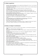
Страница 14: ...ll not access the panel Warn those in charge of maintenance of any running irregularities of parts or systems 2 2 Safety warnings for maintenance Before performing any maintenance and or cleaning the...

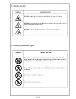
Страница 15: ...cal or moving parts 2 3 Danger design 2 4 General prohibition signs SYMBOL IDENTIFICATION Do not remove safety devices or guards temporary removal of machine safety guards and devices shall be done on...

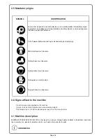
Страница 16: ...rn Safety shoes must be worn Safety helmet must be worn Safety gloves must be worn Ear protection must be worn 2 6 Signs affixed to the machine Do not remove signs applied to the machine All sign shal...

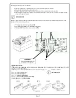
Страница 17: ...stic Additional spindles are to be decided at the moment of purchase n 11 independent Vertical spindles A n 4 1 Horizontal heads with 1 spindles each B n 1 Blade 120 thickn 4mm max 6 mm C Applicable t...

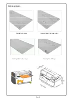
Страница 18: ...Page 18 Working examples Running holes under Running holes in the head axis x Running hole for hinge Running hole 4 side axis y...

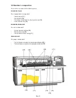
Страница 19: ...clamps in feed fence for side stop reference 3 Front stop reference 4 IN FEEDING PANEL UNIT This unit is composed of Clamps for panel catching 5 Rolls counter roller 6 Linear guide for clamps sliding...

Страница 20: ...group is composed of The boring head including bits 10 The boring head is composed of n 11 independent Vertical spindles 32 mm of step A n 4 1 Horizontal heads with 1 spindle each B n 1 blade 120 thi...

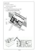
Страница 21: ...aphical programming the approach of the working group the console that includes the screen and keyboard a ground plane Board includes Machine integrated control panel Industrial PC Model Microsipu Win...

Страница 22: ...xis Y side pusher sliding Axis Y boring head movement controlled axis Axis Z vertical movement of the clamping Axis Z vertical movement pressors Axis Z vertical movement of boring head controlled axis...

Страница 23: ...age 23 The side pusher sliding axis Y is manual after unlocking it by the button D pressing The boring head sliding axis Y is moved by a balls screw powered by a gear motor E E Gear motor Balls screw...

Страница 24: ...Page 24 F The closure of the clamp axis z is by a pneumatic cylinders F The clamps holding the wooden panel during the boring cycle axis z are put into motion by n 2 2 pneu matic cylinders G G...

Страница 25: ...Page 25 Vertical movement of boring head for panel drilling from the bottom axis Z is powered by a gear motor H Upstroke of spindles axis Z is powered by a ball screw I H I...

Страница 26: ...movable by the constructor are not allowed Different uses from the one declared by the constructor are not allowed Before shipment every machine passes through many tests and detailed controls With a...

Страница 27: ...in max mm 18 1000 3 8 Technical characteristic Supply voltage V 220 400 Network frequency Hz 50 60 Total power installed Kw 3 0 Spindles rotation speed rpm 3200 Panel feeding speed m min 25 X axis at...

Страница 28: ...her people from possible work injuries 4 1 Condition for standard use of machine 4 1 1 Standard condition The machine has to work indoor with a controlled with low humidity and dust expositions Differ...

Страница 29: ...t can be packed either into a wooden box or just fixed on a pallet Possible DANGER ZONES between the place of unloading and the predisposed installation area have to be previously detected and defined...

Страница 30: ...tmospheric agents such as rain snow and hail and that access is allowed to authorized personnel only Having to keep the machine stored for a longer time it is necessary to undertake further protective...

Страница 31: ...evel 0 05 mm m accuracy and a rectified angle plate 0 01 mm INFORMATION INFORMATION After having positioned the machine on the assigned area do start leveling by following the below stated in structio...

Страница 32: ...oltage is the right one by checking electrical data stated on the machine plate Do not switch on the machine before having checked the compliance with following electrical require ments possible damag...

Страница 33: ...install a magnetic filter If disturbs are more than 10 please install a voltage stabilizer 4 6 2 Ground phase connection The grounding of all metal parts of the machine is safely ensured by insulated...

Страница 34: ...ed any regulation The next paragraphs are about tool s replacement It s high recommended before any tool s replacement to turn off the electric and pneumatic connec tion and wear protections during ma...

Страница 35: ...screen being set to zero the axes can also be obtained with the commands listed be low Axis START then finally executed command the LEDs zero setting all become green and the car is ready to work The...

Страница 36: ...n be used only by those who enabled this feature This password is to ask the manufacturer of the machine if required to do software updates and machine parameters Confirm the password with OK In the T...

Страница 37: ...1 to access the screen of the tool head Do not use normally configurations CONF 2 and 3 The configuration of the head is visible as a whole and to the right you can see the data table utensils Graphi...

Страница 38: ...nsert Tool In the configuration screen head can intervene to change tools Remove Insert Tool In the figure above you can see the data of the selected tool This serves to control and for changes to be...

Страница 39: ...u you can enter nell ambinte CAD 4 to create machining programs modificace panels Full reference see Manual CAD 4 Home Screen CAD 4 with preset icons to Macro drilling excavation With the command New...

Страница 40: ...error message View of the zero side of the panel and at the bottom left is shown the geometric reference to the departure of the shares according to the coordinate axes The joke Pin X is inserted by...

Страница 41: ...Page 41 Selection from the menu of a Macro drilling according to the working requirements Table setting the position and size hole holes to be drilled Macro Single drill Macro INFORMATION...

Страница 42: ...Page 42 Tool selection Command to select the type of tool Tool selection suitable for machining drilling and or excavation Tool Type Select the desired tool Tool type for working set...

Страница 43: ...le Programmed drill example Modify Copy Erase The programmed machining can be edited later using the commands Modify Copy Erase In the most frequent case proceed to copy the hole in the other position...

Страница 44: ...ple of the hole to be copied Selected drill copy Position of the hole on the corner copied reported 1 Drill position Corner 1 reference Selected drill to copy Corner 2 reference Drill position Corner...

Страница 45: ...e hole reportedly copied the corner 3 Corner 3 reference Drill position Position of the hole reportedly copied corner 4 Corner 4 reference Drill position Corner 3 reference Drill position Corner 4 ref...

Страница 46: ...Page 46 Example of machining on the sides of the panel showing the position of the Cartesian axes which changes depending on the side panel see selection View side 1 Example View side zero with drill...

Страница 47: ...of the panel with all the holes set up at this point of the program On the zero and also on side 1 High lights the selection icons in the upper side panel View Side And possible to select the icon to...

Страница 48: ...Page 48 Example of side 3 Side 3 Note the position of the axes that change position depending on the cho sen side of the panel Example setting Corner 1 side 3 panel and data processing...

Страница 49: ...el with work planned by side zero side Window for saving the Save As the program of the panel cutout Automatically opens the folder to save programs and should be given an identifying name to the prog...

Страница 50: ...ewrites inside the machine language program ISO The central window of the screen displays the processing and errors in writ ing or setting The window above the Diagnostic Application indicates in red...

Страница 51: ...n a separate work The distinct serves to create a list of proc essing programs that together give the possibility to obtain a series of processed panels useful for the con struction of a movable whole...

Страница 52: ...Page 52 I f you select the command New Job list you start creating a new list To enter the machining programs select the command in the window Select Source New Joblist Select Souce...

Страница 53: ...lection of the program to enter Programs explorer the preview panel chosen the working set The selected program is then created in the new bill Using the same procedure you can enter other pro grams P...

Страница 54: ...of programs included then you must define the quantity for each panel Preset and any com ments of your own The final phase of the new bill is created is saved with name Save As The lists are saved in...

Страница 55: ...green botton The bar of the bill in question will be colored in red and the machine will prompt you the first panel visible in the job list Example list of panels in the selected list Label 10 20 30 e...

Страница 56: ...Page 56 5 1 2 4 START SINGLE PROGRAM Select a program from the command single Automatic and then Axis From the Program in the drop down menu appear existing programs Select a program and PUSH Open...

Страница 57: ...panel toward the opera tor ie exhaust front Front Download To have the drain back Back Download press the button at the top right With option Back Download enabled Processing cycle at the end of the...

Страница 58: ...me the processing of a mirrored panel determined One can choose to mirror the panel according to the X axis or the axis Y The Ribattuta is activated and or deactivated at any time either on a single p...

Страница 59: ...Page 59 5 1 2 8 SHUTDOWN MACHINE Window standard Windows XP option Turn Off Computer Command Shutdown ILENIA Command Ok...

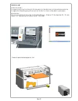
Страница 60: ...stop down 7 Press selector green A to start the drilling cycle 5 2 2 Emergency stop Facing an emergency situation press the emergency button to stop the machine 5 2 3 Restart after emergency stop To r...

Страница 61: ...cal and accurate maintenance is the essential condition to ensure longlasting efficiency and high reliability of the machine It is advisable that the below stated maintenance operations are carried ou...

Страница 62: ...condensate can be removed and conveied into a 6 4 diameter flexible pipe with direct connection to a drain cock 6 1 6 Check and regulation of the air pressure Upgrade working pressure by turning the...

Страница 63: ...OSO32 ISO HM DENISON HF 0 1 2 VICKERS CINCINNATI P68 Equivalent oils SHELL TELLUS OIL 32 AUTOMATIC Axis Y Z lubrificated EVERY 2000 HOURS USE Daily control Visual control machine Machine cleaning Eve...

Страница 64: ...cants disposal For lubricants disposal follow the below stated instructions Empty the grease cups Clean the grease residues that may have formed on the machine guides by using a cloth Give collected l...

Страница 65: ...Page 65 Page intentionally left blank...

Страница 66: ...Page 66 Maggi Technology Via delle Regioni 299 Woodworking machinery 50052 Certaldo Fi Italia Tel 39 0571 63541 Fax 39 0571 664275 E mail service maggi technology com Development by MAGGI TECHNOLOGY...

Отзывы: