© 2014 tvONE, 2791 Circleport Drive, Erlanger KY 41018 USA
Americas: 859-282-7303, EMEA: +44 (0)1843 873322, email:
www.tvone.com
Document # 5310270-01 Rev-05 (12/02/2014)
Page 2 of 2
Sync-mode Options:
The DVI-TX is factory-configured for Fixed-Sync mode. This is the required mode for compatibility with the
companion MVII-DVI-Rx-1K receiver which provides a DVI-D output signal. The DVI-TX is also compatible with other MultiView-II
analog receivers that provide a VGA output signal. For these analog receivers, RepliSync-II mode is preferred as it will offer the widest
range of compatibility with video formats. However, special circumstances may necessitate that one of the other sync-modes be
selected. In any case, all attached receivers
must
also be configured for the same sync-mode. Otherwise, you may not get a proper
video display output at that receiver.
(starting in normal-mode) Press and release the
CFG
button once to access configuration-mode.
CFG indicator = on
.
Press and release the
SEL
button
once
. You will now be able to change sync-mode settings.
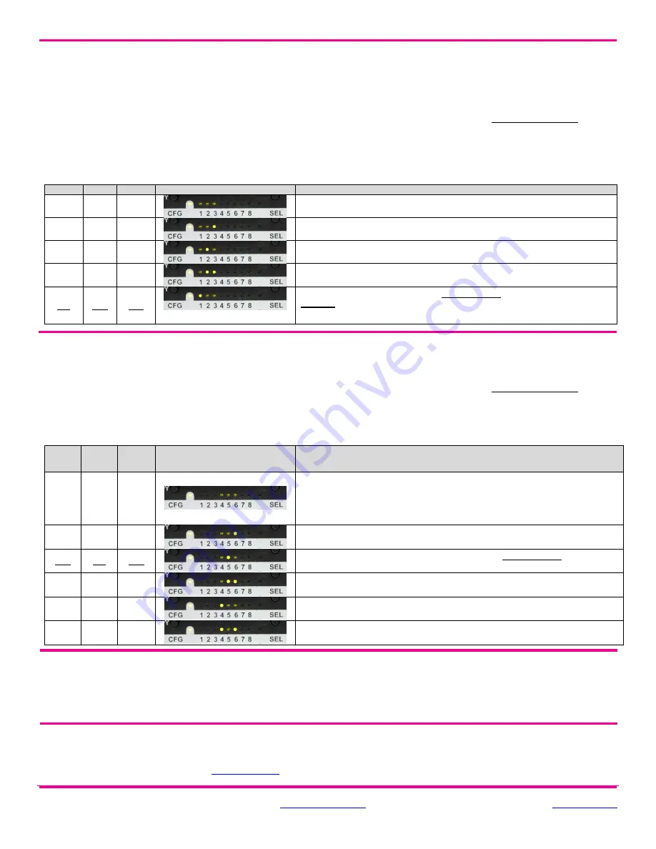
LED indicators 1-3 should be illuminated (either DIM or ON); all others (indicators 4-8) should be off.
Press the
CFG
button repeatedly to step through the available sync-mode settings as shown below.
To leave configuration-mode step through all the options OR leave the buttons untouched for 10 seconds.
LED1
LED2
LED3
Front Panel View
Sync-mode Setting
dim
dim
dim
The DVI-TX will auto-detect the required RepliSync-
I mode (“normal” or
“stretched”).
dim
dim
ON
Force RepliSync-I normal Horizontal sync. pulse encoding.
dim
ON
dim
Force RepliSync-
I “stretched” Horizontal sync. pulse encoding.
dim
ON
ON
Force RepliSync-II.
ON
dim
dim
Force Fixed-Sync mode.
This is the factory-default setting.
This is the
required
mode when interfacing to a MultiViewII DVI-Rx-1K receiver.
NOTE:
All
connected MultiView receivers must also be in fixed-sync mode and with legacy units requiring the
appropriate H/V polarities to be selected.
4
th
Pair Options:
The DVI-TX provides several options for using the 4
th
-pair signals (pairs 1-3 are generally used for video). The
factory-default settings support analog audio (L+R summed) on the 4
th
-pair. Note that any connected MultiView receiver must be
configured with a matching 4
th
-pair operating mode. Otherwise, the desired 4
th
-pair signal will not work as expected.
Note:
If the
optional SAP daughterboard is installed then the
4
th
-pair options are fixed and unchangeable.
(starting in normal-mode) Press and release the
CFG
button once to access configuration-mode.
CFG indicator = on
.
Press and release the
SEL
button
twice
. You will now be able to change 4
th
-pair option settings.
LED indicators 4-6 should be illuminated (either DIM or ON); all others (indicators 1-3, 7 and 8) should be off.
Press the
CFG
button repeatedly to step through the available 4
th
-pair settings as shown below.
To leave configuration-mode step through all the options OR leave the buttons untouched for 10 seconds.
LED4
LED5
LED6
Front Panel View
4
th
-pair Operating Mode
Note:
if an optional daughterboard is installed these cannot be changed.
dim
dim
dim
If SAP option-module is installed:
4
th
-pair operating mode is fixed to SAP mode
and this setting cannot be changed
If the SAP option-module is not installed:
4
th
-pair signals are disabled. This
effectively “mutes” anything being sent on the 4
th
pair. This can be useful for
diagnostic purposes.
dim
dim
ON
Direct pass-through of 4
th
-pair wires (custom applications).
dim
ON
dim
External analog (L+R summed) audio. This is the factory-default mode if no
daughterboard option is installed. (-A mode).
dim
ON
ON
External S/PDIF digital audio. Input-impedance = 75-ohms.
ON
dim
dim
Simplex-serial
(“-S” mode).
ON
dim
ON
Internal S/PDIF digital audio, de-embedded from video stream.
To reset all user-configurable options back to factory-default settings:
Disconnect the DC power cable (or AC power).
Press and hold the
CFG
button.
Connect the DC power cable (or AC power). All LEDs blink 3 times
– all settings are now changed back to factory-defaults.
Release the
CFG
button.
Troubleshooting:
In many cases, problems encountered when installing
MultiView™ II extension products can be resolved by
checking the FTP cable termination. It must be pinned out according to the TIA/EIA 568B standard wiring specification. For additional
troubleshooting information, or to obtain the TIA/EIA 568B wiring specifications please refer to the latest version of the
MultiView™ II
DVI-TX User Guide, downloadable from
www.tvone.com
.


