Product Notes
Reading Intervals
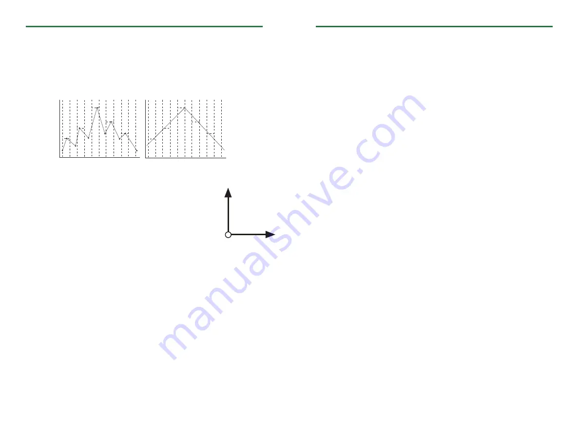
The UltraShock measures pressure, temperature, humidity and tri-axial shock. When the
device is running, the shock parameter samples at 512Hz and at the user specified reading
rate, the device writes the peak values (g-force) from the samples to memory.
For Example:
Pressure, temperature and humidity readings are taken at the user specified reading rate
up to a maximum of 2 seconds intervals.
Axis Orientation
When the UltraShock is laying flat, with the label facing up, the
x-axis indicates left to right direction and will read ~0g when
still. The y-axis reads in a top to bottom direction and reads ~0g
when still. The z-axis reads perpendicular to the other two axis,
and will read ~1g when still.
Device Maintenance
Battery Replacement
Materials:
3/32” HEX Driver (Allen Key) and a Replacement Battery
(U9VL-J)
- Remove the cover from the device by unscrewing the four screws.
- Remove the battery from its compartment and unsnap it from the connector.
- Snap the new battery into the terminals and verify it is secure.
- Replace the cover taking care not to pinch the wires. Screw the enclosure back together
securely.
Note: Be sure not to over tighten the screws or strip the threads.
Recalibration
The UltraShock standard calibration is performed at one temperature point at 25°C, two
humidity points at 25%RH and 75%RH, two pressure points at 15PSI and 27-30PSI and 0g
for the x-axis, 0g for the y-axis and 1g for the z-axis.
Note: The shock parameters are not traceable to NIST.
Pricing:
Recalibration traceable to NIST
$156.00
Recalibration
$136.00
Additional Services:
As Found Data
$15.00 per channel
Verification Point
$15.00 per point
Prices and specifications subject to change. See MadgeTech’s terms and conditions at www.madgetech.com
To send the devices back, visit www.madgetech.com, select
Services
then
RMA Process
.
UltraShock
Product Quick Reference Card
Installation Guide
Installing the Interface cable
- IFC200
Insert the device into a USB port. The drivers will install automatically.
Installing the software
Insert the Software CD in the CD-ROM Drive. If the autorun does not appear, locate the
drive on the computer and double click on
Autorun.exe
. Follow the instructions provided
in the Wizard.
Connecting the data logger
- Once the software is installed and running, plug the interface cable into the data logger.
- Click the
Communication Menu
, then
Auto Configure Port
.
- After a moment, a box will appear stating a device has been found.
- Click
OK
. The
Device Status
box will appear. Click
OK
.
- At this point, communications have been configured for your logger. These settings can
be found under the
Communication Menu
.
Note: For additional installation instructions refer to your “
Data Logger & Software Operating Manual”.
Device Operation
Starting the data logger
- Click
Device Menu
then
Start Device
.
- Choose the desired start method.
- Choose the start parameters by selecting a
Reading Rate
suitable for your application.
- Enter in any other desired parameters and click
Start
.
- A box will appear stating the data logger has been started. Click
OK
.
- Disconnect the data logger from the interface cable and place it in the environment to
measure.
Note: The device will stop recording data when the end of memory is reached or the device is stopped. At this point the
device cannot be restarted until it has been re-armed by the computer.
Downloading
data
from a
data
logger
- Connect the data logger to the interface cable.
- Click the
Device Menu
then
Read Device Data
. This will offload all recorded data onto
the PC.
Sampled Data:
Recorded Data:
Y-Axis
Z-Axis
X-Axis


