background image

12

ES

FR

EN

IT

XVP - XVPC.../NC

Madas Technical Manual

 - 1|1.2aX - REV. 1 of 10

th

 Sep 2020

Common procedures (threaded and flanged devices): 

• In accordance with EN 161 a suitable filter must be installed upstream of a gas closing safety device; 
• With outdoor installation, it is advisable to provide a protective roof to prevent rain from damaging the electrical parts of 

the device;

• Prior to carrying out any electrical wiring operations, make sure that the mains voltage matches the supply voltage indicated 

on the product label;

• Cut out power prior to proceeding with wiring;
• According to the plant geometry, check the risk of explosive mixture arising inside the piping;
• If the solenoid valve is installed near other devices or as part of an assembly, compatibility between the solenoid 

valve and this other device must be evaluated beforehand;

• Avoid installing the solenoid valve near surfaces that could be damaged by the coil temperature. 

ATTENTION

the surface temperature could cause contact burns. If it is installed in a domestic environment, it must not be 

accessible to unqualified personnel;

• The solenoid valve is suitable for installation in places at low risk of mechanical impact. Provide a protection against 

impacts or accidental contacts if the solenoid valve is accessible to unqualified personnel.

 3.2 - INSTALLATION 

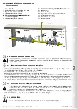
(see example in 3.4)

Threaded devices: 

• Assemble the device by screwing it, with the due seals, onto the plant with pipes and/or fittings whose threads are consistent 

with the connection being attached;

• Do not use the coil (

11

) as a lever to help you screw it on, only use the specific tool; 

• The arrow, shown on the body (

4

) of the device, needs to be pointing towards the application;

Flanged devices: 

• Assemble the device by flanging it, with the due seals, onto the plant with pipes whose flanges are consistent with the 

connection being attached. The gaskets must be free from defects and must be centred between the flanges;

• If, after installing the gaskets, there is still an excessive space in between, do not try to reduce the said gap by excessively 

tightening the bolts of the device; 

• The arrow, shown on the body (

4

) of the device, needs to be pointing towards the application; 

• Insert the relative washers inside the bolts in order to prevent damage to the flanges during tightening;
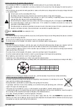
• When tightening, be careful not to “pinch” or damage the gasket;
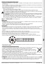
• Tighten the nuts or bolts gradually, in a “cross” order (see the example below);
• Tighten them, first by 30%, then by 60%, and finally 100% of the maximum torque (see the table below according to EN 13611);

Diameter

DN 25 DN 32 DN 40 DN 50

Max. torque (N.m)

30

50

50

50

• Tighten each nut and bolt again clockwise at least once, until the maximum torque has been achieved uniformly;

• Common procedures (threaded and flanged devices): 

• The device can also be installed vertically without prejudicing correct operation. It cannot be put in upside 

down (with the coil (

11

) pointing downwards);

• During installation, avoid debris or metal residues from getting into the device;
• To guarantee mechanical tension-free assembly, we recommend using compensating joints, which also 

adjust to the pipe’s thermal expansion;

• If the device is to be installed in a ramp, it is the installer’s responsibility to provide suitable supports or 

correctly sized supports, to properly hold and secure the assembly. Never, for any reason whatsoever, leave the weight of 

the ramp only on the connections (threaded or flanged) of the individual devices;

• In any case, following installation, check the tightness of the plant;

• ATTENTION:

 The coil is provided with a 3m long power supply cable (

1

). This cable 

CANNOT

 be replaced with a 

different one. In the event of damage, the part (coil) must be disposed of and replaced with an identical new one; Any repair 

(if possible) can only be carried out by the manufacturer;

Содержание XVP/NC

Страница 1: ...0 DN 25 DN 32 DN 40 DN 50 Attacchi flangiati Flanged connections Raccords brides Conexiones embridadas DN 25 DN 32 DN 40 DN 50 su richiesta con flange girevoli with swivel flanges on request sur deman...

Страница 2: ...s 31 Dimensioni tabella 1 34 Dimensions table 1 Dimensions tableau 1 Dimensiones tabla 1 Bobine tabella 2a 2b 34 Coils table 2a 2b Bobines tableau 2a 2b Bobinas tabla 2a 2b Livello SIL tabella 3 SIL L...

Страница 3: ...31 1 2 LEGENDA SIMBOLI ATTENZIONE Viene richiamata l attenzione su dettagli tecnici rivolti al personale qualificato PERICOLO In caso di inosservanza oltre a danni a beni materiali possono essere pro...

Страница 4: ...IDUAZIONE MODELLI XVP NC XVPC NC Apertura rapida ATEX 3G 3D XVPF NC XVPCF NC Apertura rapida regolazione portata ATEX 3G 3D 2 2 LIVELLO SIL Il livello di SIL della elettrovalvola stand alone SIL 2 qua...

Страница 5: ...pposito utensile La freccia indicata sul corpo 4 dell apparecchio deve essere rivolta verso l utenza Apparecchi flangiati Assemblare il dispositivo flangiandolo assieme alle opportune tenute all impia...

Страница 6: ...rrose Proteggere il prodotto da urti o attriti provocati da altri oggetti Verificare periodicamente l integrit del trattamento superficiale dissipativo di bobina e connettore Non installare in ambient...

Страница 7: ...senti sull impianto Verificare periodicamente che sussista una buona conduzione elettrica tra corpo valvola e linea di equipotenziale di impianto e tra bobina e linea di equipotenziale di impianto E c...

Страница 8: ...rrare il kit CPI 21 al corpo valvola 4 con apposita chiave commerciale Nell area pericolosa cablare le estremit del cavo CPI con apparecchiature omologate protette ad esplosione Es Scatola terminale c...

Страница 9: ...sa riferito all anno indicato 00001 numero progressivo riferito alla q t del lotto Mod XVPC NC DN 50 CE 51CM4100 CI A GR 2 EN 161 P max 360 mbar IP65 230 V 50 60 Hz 89 25 VA TS 20 60 C 0051 II 3G II 3...

Страница 10: ...0 Reference standards EN 161 EN 13611 EN 60079 0 7 14 15 18 31 1 2 KEY OF SYMBOLS ATTENTION Attention is drawn to the technical details intended for qualified staff DANGER In the event of inobservance...

Страница 11: ...25 with swivel flanges on request 2 1 MODEL IDENTIFICATION XVP NC XVPC NC Fast opening ATEX 3G 3D XVPF NC XVPCF NC Fast opening flow adjustment ATEX 3G 3D 2 2 SIL LEVEL The SIL level of the stand alo...

Страница 12: ...anges are consistent with the connection being attached The gaskets must be free from defects and must be centred between the flanges If after installing the gaskets there is still an excessive space...

Страница 13: ...rrosive gases chemicals salt water water or steam C3 or medium degree of environmental pollution Contact the technical department for any other application for the compatibility analysis 3 3 INSTALLAT...

Страница 14: ...ndicated in 3 2 Check tightness of the flanged threaded connections on the system Check tightness and operation of the solenoid valve Clean the product regularly to prevent dust from building up It is...

Страница 15: ...e disposed of and replaced with an identical new one Any repair if possible can only be carried out by the manufacturer Unscrew the cap 15 under the valve body 4 In place of the cap 15 screw in the CP...

Страница 16: ...order number for the indicated year 00001 progressive number referring to the quantity of the lot Mod XVPC NC DN 50 CE 51CM4100 CI A GR 2 EN 161 P max 360 mbar IP65 230 V 50 60 Hz 89 25 VA TS 20 60 C...

Страница 17: ...60079 0 7 14 15 18 31 1 2 L GENDE DES SYMBOLES ATTENTION Nous attirons votre attention sur les d tails techniques s adressant au personnel qualifi DANGER En cas de non respect il se peutqu ilyaitnonse...

Страница 18: ...antes 2 1 IDENTIFICATION DES MOD LES XVP NC XVPC NC Ouverture rapide ATEX 3G 3D XVPF NC XVPCF NC Ouverture rapide r glage du d bit ATEX 3G 3D 2 2 NIVEAU SIL Le niveau de SIL de l lectrovanne seule est...

Страница 19: ...tion avec des tuyaux dont les brides sont compatibles avec la connexion assembler Les joints doivent tre exempts de d fauts et doivent tre centr s entre les brides Si lorsque les joints sont ins r s l...

Страница 20: ...rouve en contact direct avec des gaz corrosifs des produits chimiques de l eau sal e de l eau ou de la vapeur degr de pollution ambiante C3 ou degr moyen Pour toute autre application contacter le bure...

Страница 21: ...fier l tanch it des connexions brides filet es sur l installation V rifier l tanch it et le fonctionnement de l lectrovanne Nettoyer r guli rement le produit pour viter des accumulations de poussi re...

Страница 22: ...mplac par un c ble identique et intact L ventuelle r paration si possible peut tre effectu e uniquement par le fabricant D visser le bouchon 15 sous le corps de vanne 4 Visser la place du bouchon 15 l...

Страница 23: ...iqu e 00001 num ro progressif se r f rant la q t du lot Mod XVPC NC DN 50 CE 51CM4100 CI A GR 2 EN 161 P max 360 mbar IP65 230 V 50 60 Hz 89 25 VA TS 20 60 C 0051 II 3G II 3D year 2018 Lot U1804 2185...

Страница 24: ...161 EN 13611 EN 60079 0 7 14 15 18 31 1 2 LEYENDA DE S MBOLOS ATENCI N Se llama la atenci n sobre detalles t cnicos dirigidos al personal cualificado PRECAUCI N En caso de incumplimiento adem s de da...

Страница 25: ...locas 2 1 IDENTIFICACI N DE MODELOS XVP NC XVPC NC Apertura r pida ATEX 3G 3D XVPF NC XVPCF NC Apertura r pida regulaci n de caudal ATEX 3G 3D 2 2 NIVEL DE SIL El nivel de SIL de la electrov lvula ai...

Страница 26: ...estar dirigida hacia el punto de consumo Aparatos embridados Monte el dispositivo con bridas insertando las juntas correspondientes en la instalaci n con tuber as y o racores cuyas bridas encajen con...

Страница 27: ...o de golpes o roces provocados por otros objetos Compruebe peri dicamente la integridad del tratamiento superficial disipador de la bobina y el conector No lo instale en lugares donde el producto se e...

Страница 28: ...be la estanqueidad de las conexiones embridadas roscadas en la instalaci n Compruebe la estanqueidad y el funcionamiento de la electrov lvula Limpie regularmente el producto para evitar acumulaciones...

Страница 29: ...e sufrir da os el componente debe ser eliminado y sustituido por uno id ntico y completo La reparaci n si es posible puede realizarse solo por el fabricante Desenrosque el tap n 15 debajo del cuerpo d...

Страница 30: ...a a o 2018 semana n 04 2185 n mero progresivo de pedido referido al a o indicado 00001 n mero progresivo referido a la cantidad del lote Mod XVPC NC DN 50 CE 51CM4100 CI A GR 2 EN 161 P max 360 mbar I...

Страница 31: ...1 IT EN FR ES Madas Technical Manual 1 1 2aX REV 1 of 10th Sep 2020 XVP XVPC NC fig 2 XVP NC DN 25 P max 360 mbar fig 1 XVP NC DN 15 DN 20 P max 200 360 mbar XVPC NC DN 25 P max 200 360 mbar 2 5mm 3mm...

Страница 32: ...VPC NC DN 32 DN 40 P max 200 mbar fig 4 XVPC NC DN 50 P max 200 mbar XVPC NC DN 32 DN 40 DN 50 P max 360 mbar Modelli con predisposizione per CPI switch Models with set up for CPI switch Mod les avec...

Страница 33: ...ur 17 Rondelle aluminium 18 Bague de r glage CPI 19 Serre c ble 20 crou de fixation CPI 21 Kit CPI fig 1 2 3 y 4 1 Cable de alimentaci n 2 Junta t rica de estanqueidad de la tapa 3 Muelle de cierre 4...

Страница 34: ...L DN 50 FL 200 360 230 238 253 165 67 5 170 5 185 5 178 Le dimensioni sono indicative non vincolanti The dimensions are provided as a guideline they are not binding Les dimensions sont indicatives non...

Страница 35: ...VA 16 VA 24 V 50 Hz BO 0417XFAC BO 0417XFAC 24 V 50 Hz YES 110 V 50 60 Hz BO 0427XFAC BO 0427XFAC 110 V 50 60 Hz YES 63 VA 20 VA 230 V 50 60 Hz BO 0437XFAC BO 0437XFAC 230 V 50 60 Hz YES 54 VA 18 VA...

Страница 36: ...ure CCF in points 75 Safe Failure Fraction SFF in 65 Expected Lifetime Cycles B10d 251278 Expected Lifetime T10d years 87 Probability of Dangerous Failures PFHD 1 h 1 33E 07 Performance Level PL d Saf...

Страница 37: ...0 mbar Diagramme de perte de charge calcul avec P1 50 mbar Diagrama de p rdidas de carga calculado con P1 50 mbar dv densit relativa all aria dv density relative to the air dv densit relative l air dv...

Страница 38: ...uant les connexions A adir la letra V a continuaci n de las cifras que indican los di metros de conexi n Es E g Ex Ej XVP02V 208 CATAFORESI CATAPHORESIS CATAPHOR SE CATAFORESIS Aggiungere la lettera K...

Страница 39: ...3 204 24 Vdc XVP03 205 24 V 50 Hz XVP03 203 110 V 50 60 Hz XVP03 202 230 V 50 60 Hz XVP03 208 XVPC NC DN 25 12 Vdc XVPC04 201 XVPC25 201 12 V 50 Hz XVPC04 204 XVPC25 204 24 Vdc XVPC04 205 XVPC25 205 2...

Страница 40: ...NC DN 25 12 Vdc XVPC04 001 XVPC25 001 12 V 50 Hz XVPC04 004 XVPC25 004 24 Vdc XVPC04 005 XVPC25 005 24 V 50 Hz XVPC04 003 XVPC25 003 110 V 50 60 Hz XVPC04 002 XVPC25 002 230 V 50 60 Hz XVPC04 008 XVPC...

Страница 41: ...switch Avec CPI switch Con microinterruptor CPI Codice Code Code C dice Codice Code Code C dice DN 15 Tutti All Tous Todos XVP020066 XVP020036 DN 20 Tutti All Tous Todos XVP030066 XVP030036 DN 25 Tut...

Страница 42: ...ch With CPI switch Avec CPI switch Con microinterruptor CPI Codice Code Code C dice Codice Code Code C dice Codice Code Code C dice DN 15 Tutti All Tous Todos XVPF02 XVPF020066 XVPF020036 DN 20 Tutti...

Страница 43: ...ur interrupteur CPI Kit CPI instalable nicamente en electrov lvulas expresamente preparadas para poder conectar el micro interruptor de final de carrera CPI Modello Model Mod le Modelo P max bar Attac...

Страница 44: ...ons le droit de toute modification technique et constructive Nos reservamos el derecho de realizar cualquier cambio t cnico y estructural Sede legale Via V Moratello 5 6 7 37045 Z A I Legnago VR Italy...

Отзывы: