


Macurco
TM
Macurco RD-24 Manual
REV
–
1.0.0
[34-8708-4770-1]
17
|
P a g e
6.1
Read Configuration
Device configuration is indicated by 2 bytes.
bit
15
bit
14
bit
13
bit
12
bit
11
bit
10
bit9 bit8
bit
7
bit6 bit5 bit4
bit
3
bit2 bit1 bit0
Module # 4
Module #3
Module #2
Module #1
0000 = relays
0000 = relays
0000 = relays
0000 = relays
0001 = analog outputs
0001 = analog outputs 0001 = analog outputs
0001 = analog outputs
0010 = analog inputs
0010 = analog inputs
0010 = analog inputs
0010 = analog inputs
0011 to 1110 - future
0011 to 1110 - future
0011 to 1110 - future
0011 to 1110 - future
1111 = No exp. board
1111 = No exp. board
1111 = No exp. board
1111 = No exp. board
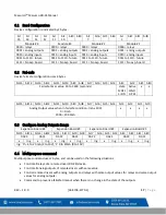
6.2
Fail-safe
Device fail safe configuration uses 4 bytes.
bit15 bit14 bit13 bit12 bit11 bit10 bit9 bit8 bit7 bit6 bit5 bit4
bit3
bit2
bit1 bit0
Fail safe timer value 30 to 3600 (seconds)
state
0=OFF
1=ON
Active
0=NO
1=YES
x
x
bit15 bit14 bit13 bit12 bit11 bit10 bit9 bit8 bit7 bit6 bit5 bit4
bit3
bit2
bit1 bit0
Analog Output value when in fail safe condition: (mA x 100)
0 = 0mA
2000 = 20.00mA
x
x
x
x
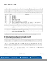
6.3
Configure Analog Outputs Range
Expansion Board #4
Expansion Board #3
Expansion Board #2
Expansion Board #1
bit15 bit14 bit13 bit12 bit11 bit10 bit9 bit8
bit7
bit6 bit5 bit4 bit3
bit2 bit1 bit0
DAC2
DAC1
DAC2
DAC1
DAC2
DAC1
DAC2
DAC1
x
rng
x
rng
x
rng
x
rng
x
rng
x
rng
x
rng
x
rng
rng
: ‘0’ –
4 to 20 mA (2 to 10V), ‘1’ 0 to 20mA (0 to 10V)
6.4
Multipurpose command
Multipurpose command uses 2 bytes, and can be used on the following situations:
•
Control all relays of a remote driver (RD-24) device.
•
Control all analog outputs of remote drivers with same value.
•
Control remote drivers with analog outputs and relays with same output values for relays and same output
values for analog outputs.
•
Command to prevent a failsafe timeout when there is no change in the state of the outputs.


