2
2
MACOM Technology Solutions Inc. (MACOM) and its affiliates reserve the right to make changes to the product(s) or information contained herein without notice.
Visit
for additional data sheets and product information.
For further information and support please visit:
DC
-
0023867
2
MASW-011148
Rev. V1
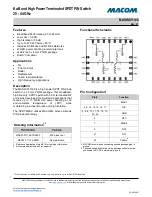
Ka-Band High Power Terminated SPDT PIN Switch
20 - 44 GHz
Electrical Specifications:
Freq. = 20
-
44 GHz, T
A
= 25°C, V
CC
= +4 V @ 28 mA /
-
15 V @ 0 mA, Z
0
= 50
Ω
Parameter
Test Conditions
Units
Min.
Typ.
Max.
Insertion Loss
21
-
28 GHz
28
-
33 GHz
33
-
41 GHz
dB
—
1.0
0.9
1.3
1.5
1.6
2.0
Isolation
5
21
-
28 GHz
28
-
33 GHz
33
-
41 GHz
dB
—
40
40
38
35
35
32
Input / Output Return Loss
On state
21
-
28 GHz
28
-
33 GHz
33
-
41 GHz
dB
—
16
18
15
—
RF1, 2 Return Loss,
Off state
21
-
28 GHz
28
-
33 GHz
33
-
41 GHz
dB
—
7
11
14
—
Switching Speed
-
T
ON
50% DC to 90% RF
ns
—
26
—
Switching Speed
-
T
OFF
50% DC to 10% RF
ns
—
27
—
Rise Time
-
T
RISE
10% to 90% RF
ns
—
8
—
Fall Time
-
T
FALL
90% to 10% RF
ns
—
11
—
CW Input Power
6
-
25 V @ +85°C
dBm
—
41.2
—
DC Reverse Bias Voltage
6
—
V
-
32
-
15
-
5
Reverse Bias Current
6
-
15 V
nA
—
25
500
Forward Bias Current
+4 V
mA
23
26
28
5.
Isolation defined with 1 port in low loss state.
6.
DC Reverse bias voltage should be determined based on working conditions. For example, recommended min of
-
25 V @ 41.2 dBm input
power. For lower power applications, a less negative voltage can be used. R. Caverly and G. Hiller,
“
Establishing the Minimum Reverse
Bias for a P
-
I
-
N Diode in a High Power Switch,
”
IEEE Transactions on Microwave Theory and Techniques, Vol.38, No.12, December 1990.


