


10
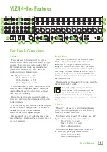
VLZ4 4•Bus
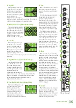
5. Stereo Returns 1-2
The stereo (aux) returns are designed for 1/4" TRS
balanced or 1/4" TS unbalanced signals, from -20 dB to
+20 dB. They allow the stereo processed output from
external effects processors or other devices to be added
to the main mix.
Level adjustment of the incoming signals is made with
the stereo return controls [54].
You may also use these inputs to add any stereo
line-level signals to your main mix, so it could be
another line-level source, not just an effects processor.
If you are connecting a mono source, use the left
(mono) stereo return input, and the mono signals will
appear on both sides of the main mix.
6. Tape Ins / Outs
The stereo unbalanced RCA inputs allow you to play
a CD player, iPod
®
dock, or other line-level source.
The tape in jacks accept an unbalanced signal using
standard hi-fi hookup cables.
The stereo unbalanced RCA outputs allow you to
record the main stereo mix onto a hard disk recorder
or automatic CD burner, for example. This lets you
make a recording for posterity/archive/legal purposes
whenever the band gets back together again.
The tape output is the stereo main mix, and it is not
affected by the main mix level control [75].
The output
could also be used as an extra set of main outputs for
feeding another zone.
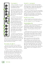
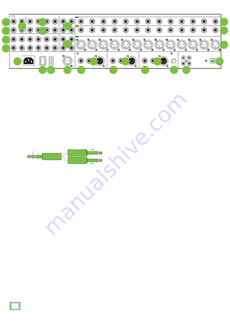
3. Insert
These unbalanced 1/4" jacks are for connecting serial
effects processors such as compressors, equalizers,
de-essers, or filters. The insert point is after the gain
control [23] and low cut filter [24], but before the
channel’s EQ [31-36] and level [43].
The channel signal
can go out of the insert jack to an external device, be
processed and come back in on the same insert jack. To
do this requires a standard insert cable that must be
wired thusly:
Tip = Send (output to effects device)
Ring = Return (input from effects device)
Sleeve = Common ground
Insert jacks may be used as channel direct outputs;
post-gain, and pre-EQ. See the connector section on
page 30 (figure G) showing three ways to use insert
cables.
4. Stereo Line Ins
The stereo line inputs are designed for 1/4" TRS
balanced or 1/4" TS unbalanced signals. They may
accept any line-level instrument, effects device, CD
player, etc.
Level control is available -20 dB to +20 dB if you are
connecting a mono source. Use the left (mono) stereo
return input, and the mono signals will appear on both
sides of the main mix.
tip
This plug connects to one of the
mixer’s Channel Insert jacks.
ring
tip
ring
sleeve
SEND to processor
RETURN from processor
(TRS plug)
POWER
ON
PHANTOM
ON
3
2
1
2
1
2
1
6
5
4
3
2
1
6
5
4
3
2
1
4
SUBGROUP OUTS
BAL / UNBAL
SUBGROUP INSERTS
TIP SEND, RINGRETURN
AUX INSERTS
TIP SEND, RING RETURN
AUX SENDS
BAL / UNBAL
3
2
1
4
L
R
MONO
L
R
MONO
STEREO RETURNS
BAL / UNBAL
21/22
23/24
BAL / UNBAL
BAL / UNBAL
MONITOR
MONO
MONITOR
L
R
100 - 240 V
50 - 60 Hz 55W
TALKBACK
MIC
RIGHT
MAIN OUT
INSERT
LINE
LEFT
MAIN OUT
INSERT
LINE
MONO
MAIN OUT
INSERT
LINE
LEVEL
OUTPUT
L
USB
R
L
R
TAPE
OUT
IN
TIP SEND
RING RETURN
TIP SEND
RING RETURN
TIP SEND
RING RETURN
BAL / UNBAL
BAL / UNBAL
BAL / UNBAL
20
20
20
19
19
19
18
18
18
17
17
17
16
16
16
15
15
15
14
14
14
13
13
13
12
12
12
11
11
11
10
10
10
9
9
9
8
8
8
7
7
7
6
6
6
5
5
5
4
4
4
3
3
3
2
2
2
1
1
1
ONYX MIC PREAMPS
LINE
(BAL / UNBAL)
INSERTS
(TIP SEND, RING RETURN)
L
INE
(BAL / UNBAL)
I
NSERTS
(TIP SEND, RING RETURN)
ONYX MIC PREAMPS
UNBALANCED
REVISION
SERIAL NUMBER
REPLACE WITH THE SAME TYPE FUSE AND RATING.
DISCONNECT SUPPLY CORD BEFORE CHANGING FUSE
UTILISE UN FUSIBLE DE RECHANGE DE MÊME TYPE.
DEBRANCHER AVANT DE REMPLACER LE FUSIBLE
WARNING:
TO REDUCE THE RISK OF FIRE OR ELECTRIC
SHOCK, DO NOT EXPOSE THIS EQUIPMENT TO RAIN OR
MOISTURE. DO NOT REMOVE COVER. NO USER SERVICEABLE
PARTS INSIDE. REFER SERVICING TO QUALIFIED PERSONNEL.
AVIS: RISQUE DE CHOC ELECTRIQUE — NE PAS OUVRIR
THIS DEVICE COMPLIES WITH PART 15 OF THE FCC RULES FOR THE U.S. AND THE ICES-003 FOR CANADA. OPERATION
IS SUBJECT TO THE FOLLOWING TWO CONDITIONS: (1) THIS DEVICE MAY NOT CAUSE HARMFUL INTERFERENCE, AND
(2) THIS DEVICE MUST ACCEPT ANY INTERFERENCE RECEIVED, INCLUDING INTERFERENCE THAT MAY CAUSE
UNDESIRED OPERATION.
+6
U
3
14
20
2
13
1
16
11
17
12
22
7
7
9
18
21
19
4
15
5
10
8
8
8
6


