8
Mackie Industrial White Paper
Noise Sensing
September 2000
would represent a 1:1 noise level versus program level change.
You can start to see the exibility of this system (see Chart 1).
By having control over the program operating window (
MG
and
GR
) and the noise window (
NT
and
NR
), the user can
actually move the noise window with respect to the program
operating window and visa versa. In this way, the system can
be set to be “sensitive” to small noise changes or “insensitive”
to large noise changes and everything in between.
3.2 Attack and Release Parameters
The
Attack
parameter denes the time, in seconds, it takes for
the
Program Gain
to increase by 40dB. Likewise, the
Release
parameter denes the time it takes for the
Program Gain
to
decrease by 40dB. The combination of these two parameters
gives the user the ability to “average” the noise to provide
a relatively constant
Program Gain
over time. Otherwise,
with short attack and release times (i.e. the default settings),
the user will hear every program level shift as it relates to
a specic noise level shift. To keep impulsive noise bursts
from affecting the program level, a good setting would be
an
Attack
=20 seconds and
Release
=20 seconds. This would
avoid the impulsive change but would still allow a fairly
“responsive” program level change as it relates to a noise
level change (~40 seconds). In a plant setting where there are
numerous pages and “break time” buzzers, setting the
Attack
and
Release
Time
on the order of minutes, will eliminate
program level changes on all but the average long-term noise
level. There may be a situation where you want a long
Attack
and a short
Release Time
or visa versa. For example: in a plant
with background music, equipment may be turned on sequen-
tially (relatively slowly) in the morning but in the evening
all are switched off together. A long
Attack
but short
Release
Time
might be advantageous by allowing the music level to
decrease instantly when the noise level fades.
3.3 Bar Graphs/Metering
The main screen of the SP-Control™ Palm™ application has
four meters that allow the user to monitor levels during setup
and normal operation (see Figure 2). “
PI
” is the
Program
Input
meter and it indicates the input level into the DSP (range
from 0 to 60dB). During setup before
Auto Calibration
, the
user needs to ensure that the input program source has suf-
cient signal level by monitoring this meter. The input level
should be between 0 and –10dB during the loudest portions
of the program material. “
MI
” is the
Microphone Input
meter.
This meter indicates the ambient microphone input level in
a range from 0 to 60dB. Again, before an
Auto Calibration
is executed, ensure that the microphone level is within the
range from 0 to –10dB for the loudest noise plus program
expected. On the rear panel of the SP2400/1200 ampliers,
there is an “ambient mic” trim potentiometer. Adjust this trim
potentiometer (0-55dB) to get the proper levels as indicated by
the “
MI
” meter. Note that the SP-DSP1™ does not have a mic
preamp. Therefore, it is essential that the ambient microphone
input receives a line-level signal (1 V RMS Full-scale). The
third meter from the left as shown on the SP-Control™ screen
is the “
PG
” meter which is the
Program Gain
. This meter
represents the gain (0 to 60dB) that algorithm applies to
the
Program Input
. The last meter is the “
PO
” which is the
Program Output
meter. This is the level at the output of the
SP-DSP1™ (0 to 60dB). The following condition will always
be true:
Prog. Output level = Prog. Input level + Prog. Gain (in dB)
(5)
A good way to set the proper “
MI
” level is to select the
Bypass
button on the main screen. Then, while playing typical program
material, adjust the microphone preamp trim potentiometer on
the rear panel of the SP2400/1200 until the “
MI
” meter is within
0 to –10dB. This allows us to adjust the level while the micro-
phone is “hearing” both the program material plus the noise so
that we do not inadvertently clip the SP-DSP1™ microphone
input during calibration. Clipping the microphone or program
input (ADC) will produce erratic controller behavior and should
be avoided.
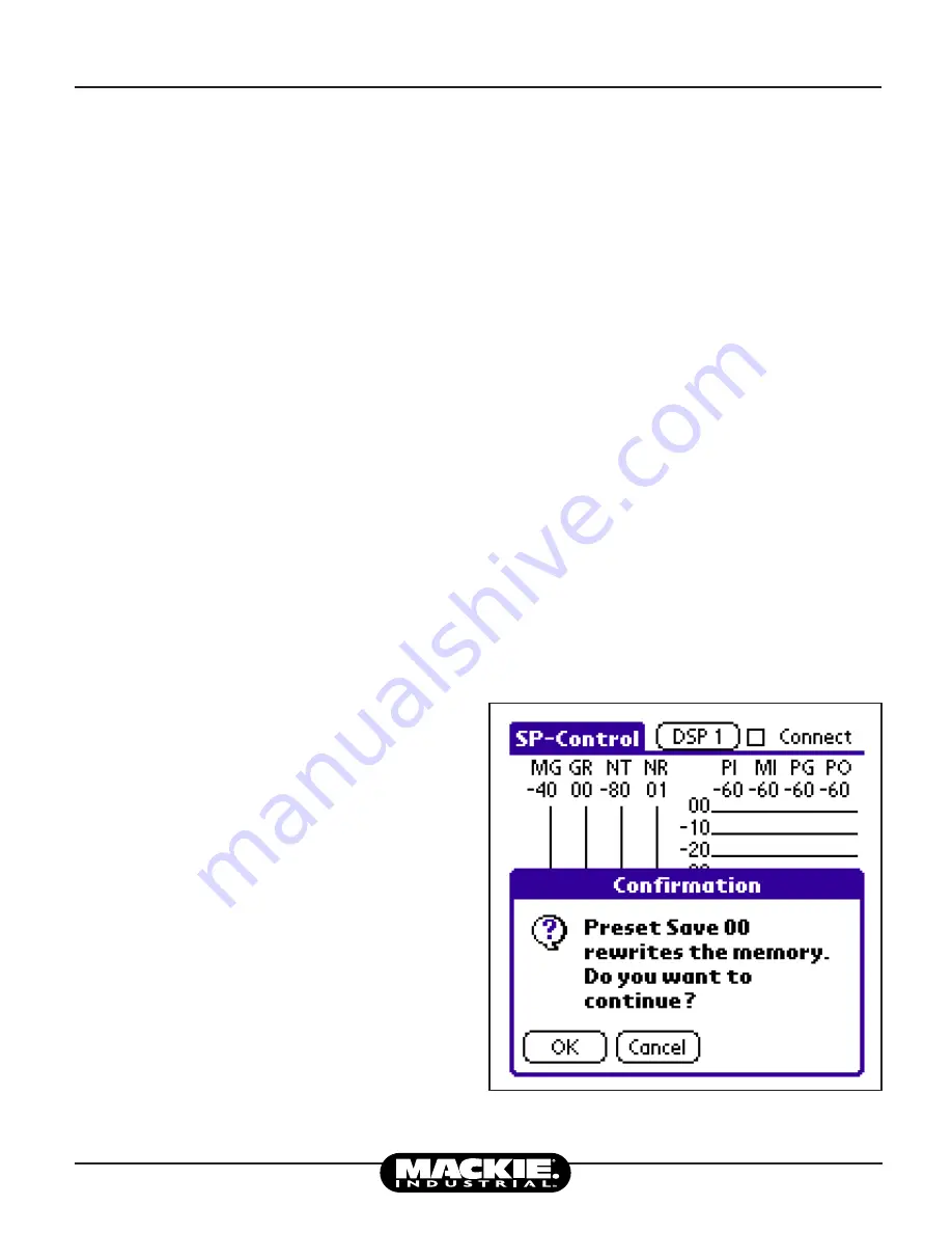
Figure 3: SP-Control™ Save Conrmation