background image

13

Operation Guide

Oper

a

tion 

Guide

Sync Card and Cables - Word Clock and Digital Synchronization

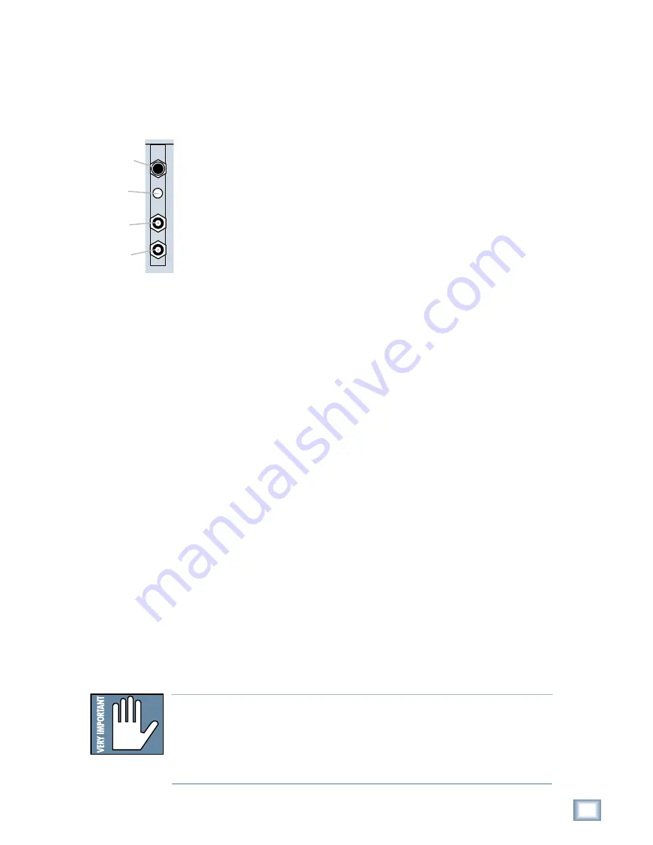
The Sync Card provides ports to synchronize the MDR24/96’s sample clock and
time/transport position to other equipment. The functions of the jacks and switch,
from top to bottom are:

•   SMPTE Input / Output – This 1/4" TRS jack serves as an input when

slaved to incoming SMPTE time code, and as an output when generating
SMPTE time code to synchronize other devices with the MDR24/96.

   Termination Switch – This pushbutton switch selects the termination

impedance of the Word Clock / Video Input jack. When the switch is out,
the impedance is 3.3k

 (bridging); when in, the impedance is 75

(terminated).

•   Word Clock / Video Input – This BNC jack receives either word clock,

composite video, or video blackburst as determined by the MDR24/96
Sample Clock setting. Use this input when the MDR24/96 is operating as a
word clock slave.

•   Word Clock Output – This BNC jack transmits word clock to other devices

in the system when the MDR24/96 is configured as the clock master.

Whenever digital audio connections are made between devices, the sample clock
of every device must run at exactly the same rate. This is usually accomplished by
selecting one device as the “master” clock source and distributing its word clock
signal to all the “slave” devices in the system. The master is configured to run
from its internal clock, and the slaves from external word clock. Some digital
interfaces are self-clocking (such as the AES input on many DAT machines) and
do not require a separate work clock connection. Others simply cannot be
configured as slaves. The master/slave designation must be made correctly for
each device to avoid the clicks and pops associated with asynchronous clocks.

Whenever time code (positional) synchronization is used, all the devices in a
system, both analog and digital, must be synchronized to a common timing (speed)
reference. This is often achieved by distributing video from a master video sync
generator (sometimes called “house sync”) to all the slave devices in the system
when word clock cannot otherwise be used. The MDR24/96, like many other
digital devices, can synchronize its sample clock to a video signal. However, video
does not provide enough timing precision to properly synchronize devices whose
digital audio paths are interconnected; word clock must be used instead.

Generally it doesn’t matter which device in a system serves as the word clock
master, except when synchronizing to time code or video. For example, if your
MDR24/96 Inputs and Outputs are connected to the Tape Inputs and Outputs of a
Mackie Digital 8•Bus console using TDIF, either the MDR24/96 or D8B can be the
word clock master. However, if you later synchronize the MDR24/96 to time code
from a VTR, you must lock the VTR and MDR24/96 to a master video sync source
and lock the D8B (which can’t sync to video) to word clock from the MDR24/96.
In this case the MDR24/96 becomes both a video slave and a word clock master.
For more detailed information on setups involving video and time code
synchronization, see the HDR24/96 Technical Reference manual, available to
download at www.mackie.com.

SYNC

NOT

WARNING

SMPTE Input/

Output

Termination

Switch

Word Clock/

Video Input

Word Clock

Output

Note: 

Note: 

Note: 

Note: 

Note:  For audio-for-video applications, the MDR24/96 can lock its word clock to
a video signal. In this configuration, there must be only one word clock depen-
dent device (The MDR24/96) locked to the video source. The MDR24/96 then
becomes the word clock master for the other digital devices in the system (for
example, a digital mixing console). Do not attempt to lock multiple digital de-
vices to the video signal, or you’ll get clicks.

Содержание MDR 24

Страница 1: ...24 TRACK 24 BIT DIGITAL AUDIO HARD DISK RECORDER Operation Guide MDR 24 MDR 24 MDR 24 MDR 24 MDR 24 96...

Страница 2: ...e des communications du Canada This product has been tested and complies with the following standards and directives as set forth by the European Union EN 55022 Radiated and Conducted Emissions EN 610...

Страница 3: ...ookups 23 Analog Hookup AIO 8 23 TDIF Hookup DIO 8 25 ADAT Optical Hookup DIO 8 or OPT 8 27 AES EBU Hookup PDI 8 30 MDR24 96 Operation 32 Project Management 32 Creating Projects 32 Opening Projects 33...

Страница 4: ...lectronics Corporation 60 Canare 60 Whirlwind 60 Appendix F Networking FTP Setup 61 Peer to Peer Networking 61 Hardware Interconnection 62 Network Configuration 62 System 1 Settings MDR24 96 63 System...

Страница 5: ...or distributors In the unlikely event that you should need to send the MDR24 96 back to Mackie for service please use the shipping box it came in This box has been specially designed to minimize dama...

Страница 6: ...uttons So we decided to lose a few along the way and hide the ones that were used less frequently as often as you visited Aunt Sadie somewhere under an LCD menu To make up for missing buttons and the...

Страница 7: ...or Cancel may bring you back to a previous menu or all the way back to the top You can also leave the menu by pressing the button that got you there its red LED will be lit to remind you where you ar...

Страница 8: ...creen saver blanks the display after ten minutes of display inactivity To re activate it press one of the large buttons or any menu button Project Information Display The following information is disp...

Страница 9: ...a removable drive using inexpensive removable 2 2 GB ORB cartridges and data transfer to another computer through the MDR24 96 s 100 Base T Ethernet port via the built in FTP server Offers two optiona...

Страница 10: ...s section describes how to install the I O cards and how to connect the MDR24 96 to your console Before you begin you should choose a location for your MDR24 96 considering the following If you re not...

Страница 11: ...nt OPT 8 The OPT 8 is a low cost ADAT Optical only version of the DIO 8 card The previous ADAT information also applies to this card PDI 8 Each PDI 8 carries four stereo pairs eight channels of digita...

Страница 12: ...the bag 5 Hold the new card so the component side faces left and line up the top and bottom edges with the white card guides Push the card all the way into the slot until its faceplate is flush with...

Страница 13: ...r time code positional synchronization is used all the devices in a system both analog and digital must be synchronized to a common timing speed reference This is often achieved by distributing video...

Страница 14: ...ing device s With the MDR24 96 configured as a slave connect the word clock out of the master ADAT Optical device to Word Clock In on the MDR24 96 AES EBU PDI 8 With the MDR24 96 as a master set the r...

Страница 15: ...as we all know hard drives involve some pretty intricate technology So don t shake the little darlin and if a tray has just come in from a freezing car or airplane cargo hold do not install it until i...

Страница 16: ...ust power cycle the Remote 48 to reset the connection Footswitch Optional For hands free do it yourself punches and other frequently used functions like Play Stop Punch In Out and Take Select connect...

Страница 17: ...input settings for each of the three I O cards 3 Press the SELECT button corresponding to each DIO 8 card and toggle the selection between ADAT and TDIF 4 Press the Page Left button to return to the p...

Страница 18: ...eight settings you have four one for each pair of channels To set the PDI 8 card options 1 Press DIGI I O to enter the DIGITAL I O Card Setup menu 2 Select Rate Convert The SAMPLE RATE CONVERT menu sh...

Страница 19: ...le some DVD disks use 96 kHz The video production folks prefer 48 kHz because their digital video recorders use 48 kHz Even though the MDR24 96 supports four Sample Rates you can only choose between t...

Страница 20: ...ght come from an inexpensive VCR by disengaging TC Chase after the MDR24 96 has found its time code related position it will free run and not sweat the unstable time code Synchronization won t be perf...

Страница 21: ...press the Right Arrow button to move to page two of the SYNC OPTIONS menu 2 Press the Pre Roll Time select button 3 Use the and select buttons to select Hours Minutes Seconds or Frames and use the DEC...

Страница 22: ...e Sample Rate to 44 1 kHz or 48 kHz 88 2 kHz or 96 kHz Select OK 4 Move to the third page of the SYNC OPTIONS menu with the Page Right button 5 Select Bit Depth Set the Bit Depth to 16 Bit or 24 Bit u...

Страница 23: ...plugs on each of the three snakes to the like numbered Submaster Tape Output jacks on the 8 Bus console This works as long as you don t record more than 8 channels at a time since the Submaster Outpu...

Страница 24: ...Sample Rate and Bit Depth according to your preference It is not necessary to set the D8B and MDR24 96 to the same sample rate since with analog connections the sample clocks on the two units are not...

Страница 25: ...the MDR24 96 the clock master connect its Word Clock Out to the D8B Word Clock In See Figure 1 MDR24 96 Settings 1 Set the Tape Input format for each DIO 8 card to TDIF and the Tape Output format to T...

Страница 26: ...IF ADAT OPTICAL Word Clock In TDIF Cables DB25 DIO 8 Cards Word Clock Out Apogee Clock I O Card TDIF Connection NOT WARNING APOGEE DIGITAL I O SYNC IN OUT TDIF ADAT OPTICAL APOGEE DIGITAL I O SYNC IN...

Страница 27: ...to the MDR24 96 Word Clock In To make the MDR24 96 the clock master connect its Word Clock Out to the D8B Word Clock In MDR24 96Settings 1 If you have DIO 8 cards installed set the Tape Input and Tape...

Страница 28: ...Digital 8 Bus DIO 8 Cards NOT WARNING APOGEE DIGITAL I O SYNC IN OUT TDIF ADAT OPTICAL APOGEE DIGITAL I O SYNC IN OUT TDIF ADAT OPTICAL APOGEE DIGITAL I O SYNC IN OUT TDIF ADAT OPTICAL MDR 24 96 Figur...

Страница 29: ...ADAT Optical Out ADAT Optical Hookup with OPT 8 APOGEE SYNC APOGEE Word Clock Out Word Clock In Word Clock Out MDR24 96 as Master Word Clock Out D8B as Master Word Clock In Word Clock Out Apogee Clock...

Страница 30: ...a clock slave set the Sample Clock to Word Clock and depress the 75 termination switch on the Sync card 2 Set the Sample Rate to 44 1 kHz or 48 kHz according to your preference Console Settings 1 If...

Страница 31: ...lock Out Word Clock In Word Clock Out MDR24 96 as Master Word Clock Out D8B as Master Word Clock In Word Clock Out Apogee Clock I O Card NOT WARNING MDR Sync Card Word Clock In Word Clock Out Use one...

Страница 32: ...down you re ready to start recording First you ll need to create a new Project Typically a Project is a song radio spot or sound effects stem for a 10 minute film reel but it could also be a live conc...

Страница 33: ...lect Open PROJECT MENU 1 New Open Save Delete Select Source Drive Internal NEXT Enter A Project Name v Project 1 New Cancel 4 The name Project 1 appears on the left side of the LCD screen A pointer v...

Страница 34: ...her way to reclaim disk space is to use the Purge Audio command This command will completely remove any audio from the hard drive that is no longer in use What does this mean Audio that you can hear i...

Страница 35: ...e the desired Project using the Dec Inc or the buttons 4 Press OK When the backup is completed either select another Project to back up or press the BACKUP button to exit It is extremely important tha...

Страница 36: ...hree times Stop STOP brings the tape to an immediate halt Stop also punches out of record and cancels master record standby TostoptheTransport Press STOP REWIND FAST FWD PLAY STOP RECORD Record All re...

Отзывы: