background image

7

Owner’s Manual

Owner’

s Manual

Front Panel

Although the functions of the knobs and  

buttons on the MCU Pro will vary depending on 

which software application is being utilized, this 

section provides an overview of the control surface 

and a general explanation of what it can do. Note 

that not all controls are implemented by each  

software platform. Check out the FAQ section on 

the Mackie website for more information:  

www.mackie.com/products/mcupro/mcupro_faq

Channel Strip

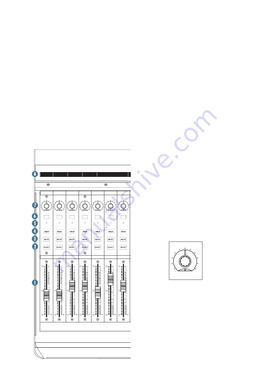
1. TOUCH-SENSITIVE FADERS

These 100mm, touch-sensitive, motorized  

faders are used to control the channel’s levels, aux 

returns, MIDI tracks, and master fader levels. The 

eight faders move relative to the activity of the 

currently selected bank of on-screen faders. 

2. SELECT 

This button selects the corresponding channel 

for channel-based editing or assignment  

commands.

3. MUTE

The MUTE button turns off the corresponding 

channel’s output signal.

4. SOLO

Pushing a SOLO button isolates that channel’s 

output signal to the mix bus in the DAW application.

Note:

 When one or more SOLO buttons are 

active, the RUDE SOLO LED next to the Time 

Display lights to signal that one or more  

channels are soloed.

5. SIGNAL

This LED illuminates when a signal is present 

in the corresponding channel.

6. REC

This button arms or disables the corresponding 

track for recording.

7. V-POT

The V-Pots serve a dual function on the Mackie 

Control, acting as a push-button and a rotary  

control. When a V-Pot is pressed, it may be used to 

change modes of operation or to change what  

appears in the display above the channel strips.

Depending on its assigned function, a V-Pot may 

be used to adjust a channel’s pan, send level, or 

plug-in parameters when rotated.

8. SCRIBBLE STRIP

This backlit LCD above the channel strips  

displays track names, plug-in parameters, and 

other information depending on the channel strips’ 

current mode of operation.

BANK

CHANNEL

SOLO

CYCLE

DROP

REPLACE

CLICK

SIGNAL

SIGNAL

SIGNAL

SIGNAL

SIGNAL

SIGNAL

SIGNAL

SIGNAL

FLIP

GLOBAL

VIEW

DISPLAY

MODIFIERS

AUTOMATION

UTILITIES

CONTROL

SHIFT

OPTION

READ/OFF

WRITE

TOUCH

LATCH

TRIM

CANCEL

SMPTE

BEATS

ENTER

SAVE

UNDO

/

ALT

NAME

VALUE

MIDI

TRACKS

INPUTS

AUDIO

TRACKS

AUDIO

INSTRUMENT

AUX

BUSSES

OUTPUTS

USER

F1

F2

F3

F4

F5

F6

F7

F8

8

7

6

5

4

3

2

1

MASTER

FADER BANKS

EQ

INSTRUMENT

PLUG-IN

TRACK

SEND

PAN/

SURROUND

VPOT ASSIGN

GROUP

MARKER

NUDGE

GLOBAL VIEW

5

U

5

10

20

30

40

50

60

10

dB

5

U

5

10

20

30

40

50

60

10

dB

+

0

5

U

5

10

20

30

40

50

60

10

dB

+

0

5

U

5

10

20

30

40

50

60

10

dB

+

0

5

U

5

10

20

30

40

50

60

10

dB

+

0

5

U

5

10

20

30

40

50

60

10

dB

+

0

5

U

5

10

20

30

40

50

60

10

dB

+

0

5

U

5

10

20

30

40

50

60

10

dB

+

0

5

U

5

10

20

30

40

50

60

10

dB

+

0

FUNCTION SELECT

UNIVERSAL CONTROL SURFACE

REC

REC

REC

REC

REC

REC

REC

REC

ASSIGNMENT

TICKS

SUB DIVISION

BEATS

BARS

SMPTE

BEATS

HOURS

MINUTES

SECONDS

FRAMES

RUDE 

SOLO

ZOOM

SCRUB

REWIND

FAST FWD

PLAY

STOP

RECORD

Содержание MCU Pro

Страница 1: ... 20 30 40 50 60 10 dB 0 5 U 5 10 20 30 40 50 60 10 dB 0 FUNCTION SELECT UNIVERSAL CONTROL SURFACE SCRUB REC REC REC REC REC REC REC REC ZOOM ASSIGNMENT TICKS SUB DIVISION BEATS BARS SMPTE BEATS HOURS MINUTES SECONDS FRAMES RUDE SOLO REWIND FAST FWD PLAY STOP RECORD 8 7 6 5 4 3 2 1 SIGNAL SIGNAL SIGNAL SIGNAL SIGNAL SIGNAL SIGNAL SIGNAL 5 U 5 10 20 30 40 50 60 10 dB 5 U 5 10 20 30 40 50 60 10 dB 5 ...

Страница 2: ...tenna Increase the separation between the equipment and the receiver Connect the equipment into an outlet on a circuit different from that to which the receiver is connected Consult the dealer or an experienced radio TV technician for help CAUTION Changes or modifications to this device not expressly approved by LOUD Technologies Inc could void the user s authority to operate the equipment under F...

Страница 3: ...e Typical Example 8 90 Duo in small club 6 92 4 95 Subway Train 3 97 2 100 Very loud classical music 1 5 102 1 105 B en and M att screaming at T roy about deadlines 0 5 110 0 25 or less 115 Loudest parts at a rock concert ATTENTION Le présent appareil numérique n émet pas de bruits radioélectriques dépassant las limites applicables aux appareils numériques de class A de class B selon le cas prescr...

Страница 4: ...I Connect the MCU Pro to the MIDI interface via two MIDI cables IN and OUT Use the MIDI 2 MAIN MIDI connections on the MCU Pro Connect the third party MIDI interface to the computer as described by the manufacturer see Hookup 2 MIDI on page 6 For both methods Connect one end of the external power supply to the MCU Pro and the other end to an AC power source between 100 VAC and 240 VAC 50 60 Hz Tur...

Страница 5: ...the thickness of the mounting plate The screw length is calculated by determining the thickness of the mounting plate and adding 0 25 inches to that for the threads to engage the pemnut in the bottom of the MCU Pro see figure below The MCU Pro weighs 16 8 lb 7 6 kg and the MCU XT Pro weighs 11 0 lb 5 0 kg so be sure to select a mounting arm or plate that can support the weight of the unit Many VES...

Страница 6: ...R POWER 3 0A 4 0A 7 5V UNIVERSAL CONTROL SURFACE EXTENDER IN MAIN OUT IN OUT IN 1 2 OUT PORT 2 PORT 3 PORT 4 EXTERNAL CONTROL USER SWITCH PORT1 EXTERNAL POWER POWER 7 5V 3 0A 4 0A UNIVERSAL CONTROL SURFACE USB Connection Digital Audio Workstation This setup provides the ultimate in DAW control 32 faders with 32 V Pots You may purchase short MIDI cables to keep the cabling neat and tidy when connec...

Страница 7: ...OT The V Pots serve a dual function on the Mackie Control acting as a push button and a rotary control When a V Pot is pressed it may be used to change modes of operation or to change what appears in the display above the channel strips Depending on its assigned function a V Pot may be used to adjust a channel s pan send level or plug in parameters when rotated 8 SCRIBBLE STRIP This backlit LCD ab...

Страница 8: ...ton to toggle between Jog and Shuttle functions for the large wheel Use the wheel for editing audio in the DAW application 14 ZOOM AND NAVIGATION BUTTONS These four arrow buttons and the zoom button are used to navigate around the graphic editor in the DAW application 15 TIME DISPLAY This display shows the time location of the project in either SMPTE or BBT bar beat ticks format BANK CHANNEL SOLO ...

Страница 9: ... MIDI IN to MIDI OUT and vice versa This appears as MIDI Port 4 in the DAW application IN MAIN OUT IN OUT IN 1 2 OUT PORT 2 PORT 3 PORT 4 EXTERNAL CONTROL USER SWITCH PORT1 INTERNAL MCU EXTERNAL POWER POWER 7 5V 3 0A 4 0A UNIVERSAL CONTROL SURFACE 21 USER SWITCH 1 and 2 These are provided for connecting a momentary footswitch to the MCU Pro that may be used to control functions such as Play Stop R...

Страница 10: ...MCU XT Pro during power up perform a variety of configuration tasks See the table below for more information Key Command Function More Information Mode Change Select 1 and 2 Page 4 and Appendix C Fader Alignment V Pot 1 and 2 Appendix B page 11 Upgrade Firmware Record 1 and 2 plus Select 1 See firmware update release notes ...

Страница 11: ...T Pro To Align the Faders 1 Power off the unit 2 Simultaneously press and hold the Channel 1 V Pot and Channel 2 V Pot buttons and power on the MCU Pro or MCU XT Pro 3 The faders move up then down for calibration The LCD then displays Entering fader alignment mode 4 The LCD displays instructions to align all faders at 40 dB Do so by moving all faders until the fader s black center lines up exactly...

Страница 12: ...Surface Guide Apple Logic Express Logic Control None User Manual Control Surface Guide Apple Final Cut Pro Logic Control None User Manual Avid Pro Tools HD LE MP HUI Pro Tools User Manual Steinberg Cubase Mackie Control Cubase Nuendo All Documentation Steinberg Nuendo Mackie Control Cubase Nuendo All Documentation Ableton Live Mackie Control Live User Manual Propellerheads Reason Mackie Control Re...

Страница 13: ...blem Visit the Support section of our website www mackie com support where you will find lots of useful information such as FAQs and other documentation You may find the answer to the problem without having to send your Mackie product away Troubleshooting No power Is it plugged in Make sure the AC outlet is live check with a tester or lamp Our next favorite question Is the power switch on If not t...

Страница 14: ... Pro 10 1 in 256 mm MCU XT Pro Depth 16 9 in 429 mm both Weight 16 8 lb 7 6 kg MCU Pro 11 0 lb 5 0 kg MCU XT Pro Disclaimer Since we are always striving to make our products better by incorporating new and improved materials components and manufacturing methods we reserve the right to change these specifications at any time without notice Mackie and the Running Man figure are registered trademarks...

Страница 15: ...60 10 dB 0 FUNCTION SELECT UNIVERSAL CONTROL SURFACE IN MAIN OUT IN OUT IN 1 2 OUT PORT 2 PORT 3 PORT 4 EXTERNAL CONTROL USER SWITCH PORT1 INTERNAL MCU EXTERNAL POWER POWER 7 5V 3 0A 4 0A UNIVERSAL CONTROL SURFACE REC REC REC REC REC REC REC REC ZOOM SCRUB REWIND FAST FWD PLAY STOP RECORD 16 5 in 419 mm 4 4 in 113 mm 16 9 in 429 mm WEIGHT 16 8 lb 7 6 kg IN OUT MIDI EXTERNAL POWER POWER 3 0A 4 0A 7...

Страница 16: ...the noncompliance within the Warranty Period to the Company at www mackie com support or by calling LOUD technical support at 1 800 898 3211 toll free in the U S and Canada during normal business hours Pacific Time excluding weekends or LOUD holidays Please retain the original dated sales receipt as evidence of the date of purchase You will need it to obtain any warranty service For full terms and...

Страница 17: ... Road NE Woodinville WA 98072 USA United States and Canada 800 898 3211 Europe Asia Central and South America 425 487 4333 Middle East and Africa 31 20 654 4000 Fax 425 487 4337 www mackie com E mail sales mackie com ...

Отзывы: