background image

DRM

12A 2000W 

12" Arr

ay

able P

ow

er

ed L

oudspeak

er

14

DRM12A 2000W 12" Arrayable Powered Loudspeaker

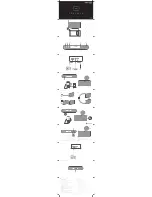
DRM12A Loudspeaker: Rear Panel Features continued...

4. XLR Input

The input channel may accept a balanced mic  

signal using an XLR connector. It is wired as follows, 

according to standards specified by the AES (Audio 

Engineering Society).

Balanced XLR Input Connector

     Pin 1 = Shield (ground) 

     Pin 2 = Positive (+ or hot) 

     Pin 3 = Negative (– or cold)

NEVER connect the output of an amplifier  

directly to the DRM12A’s input jack.  

This could damage the input circuitry!

5. XLR Output

This is a male XLR-type connector that produces  

exactly the same signal that is connected to the input 

jack located above it. Use it to daisy-chain several 

DRM12A loudspeakers together off the same signal 

source.

It is wired as follows, according to standards  

specified by the AES (Audio Engineering Society): 

Balanced XLR Output Connector

     Pin 1 – Shield (ground) 

     Pin 2 – Positive (+ or hot) 

     Pin 3 – Negative (– or cold)

See page 6 to learn more about daisy-chaining  

DRM12A loudspeakers.

2

3

1

SHIELD

COLD

HOT

SHIELD

COLD

HOT

3

2

1

INPUT

OUTPUT

PUSH FOR SETTINGS

SPEAKER CONTROL

7

6

4

5

2

1

SHIELD

COLD

HOT

3

SHIELD

COLD

HOT

3

2

1

6. LCD Display

This modern, high-resolution, all-color TFT LCD  

Display is one of the most vital features of the DRM12A 

loudspeaker. It displays loudspeaker information 

including (but not limited to) levels, array mode, 

high-pass filter, EQ and delay settings, lock / unlock 

status and other parameters.

The brightness is controllable, but  

an overall screen brightness is required  

for certain aspects of the set-up options.

7. Speaker Control Knob

This push-button rotary encoder allows you  

to access functions such as master level control  

and metering, array mode, subwoofer HPF, EQ and 

delay settings, product information and much more!

8 and 9. Dual-Angle Pole Cup

The rear pole cup [8] is for use with a single unit on 

a pole. It orients the DRM12A downward 10˚ for output 

parallel to the floor.

The front pole cup [9] serves two purposes. It angles 

the DRM12A downward 30˚ to aim at the audience  

below the loudspeaker. It may also be utilized for use 

with two DRM12As arrayed on one pole. 


PUSH FOR SETTINGS

SPEAKER CONTROL

In

+2

3-4 Long

Array Mode :

DRM SUB

Subwoofer :

9 ms

Delay :

+6

130

-7

1.25k

+10

15.5k

Low:

Mid:

High:

6

7

9

8

Содержание DRM12A

Страница 1: ...OWNER S MANUAL 2000W 12 Arrayable Powered Loudspeaker DRM12A...

Страница 2: ...ong 20 The AC Mains PowerCon connector the appliance coupler is used as the disconnect device This connector shall remain readily accessible and operable 21 The use of apparatus is in tropical and or...

Страница 3: ...XLR Input and Output Premium components and cabinet design o Road worthy 15mm plywood construction and internal bracing offers optimal acoustic performance with a touring grade textured coating and p...

Страница 4: ...gned so the transducers are positioned as close together as possible More specifically the separation between the transducers must be less than the wavelengths emitted by them This is easy to achieve...

Страница 5: ...uts on the rear panel of the DRM12A loudspeakers 4 Push the line cord securely into the subwoofer s IEC connectors and plug the other ends into grounded AC outlets The subwoofer may accept the appropr...

Страница 6: ...jack to the second DRM12A s input jack using a balanced XLR cable A short 1 2 foot cable is all that is necessary Hook up the supplied loop Neutrik PowerCon cable from the first DRM12A s AC Thru jack...

Страница 7: ...vocal reinforcement Another possibility is to place DRM12As on the stage as front or side fills This helps provide sound to the fans near the stage where they may not be adequately covered by the PA T...

Страница 8: ...gle position and the subwoofer HPF to DRM Sub Or set it to Var if not using the DRM18S It is possible to reproduce this exact same hookup in stereo for even wider and louder dispersion Simply utilize...

Страница 9: ...he left and right main outputs from the mixer to feed the main inputs of the first DRM12A on each side of the stage and mirror the rest of the system as described above Another important aspect to kee...

Страница 10: ...high frequencies in mono and the sub provides the low frequencies in mono Since three DRM12As are used the array mode should be set to the 3 4 or 3 4 long position and the subwoofer HPF to DRM Sub Or...

Страница 11: ...e hookup in stereo Simply utilize the left and right main outputs from the mixer to feed the inputs of the top boxes and mirror the rest of the system as identified above Another important aspect to k...

Страница 12: ...Top See pages 16 and 22 for more information It is possible to reproduce this exact same hookup in stereo Simply utilize the left and right main outputs from the mixer to feed the main inputs of the t...

Страница 13: ...things turned off This will reduce the possibility of any turn on or turn off thumps in the loudspeakers 2 AC Thru Jack The Neutrik PowerCon AC IN and AC THRU connectors are wired in parallel to provi...

Страница 14: ...OLD HOT SHIELD COLD HOT 3 2 1 INPUT OUTPUT PUSH FOR SETTINGS SPEAKER CONTROL 7 6 4 5 2 1 SHIELD COLD HOT 3 SHIELD COLD HOT 3 2 1 6 LCD Display This modern high resolution all color TFT LCD Display is...

Страница 15: ...avigate between the selections and push the button to open and edit the parameters In 2 3 4 Long Array Mode DRM SUB Subwoofer 9 ms Delay 6 130 7 1 25k 10 15 5k Low Mid High Main EQ Array Delay Sub Con...

Страница 16: ...mode is calculated to account for up to 100 feet of air loss compensation The top box in a flown three or four box array typically has to reach an audience that is much further away than those covered...

Страница 17: ...s you to the menu SUBWOOFER HPF 90Hz VAR VAR OFF DRM SUB SUBWOOFER HPF 90Hz VAR VAR OFF DRM SUB EQ Setup On to the bottom row now The first one listed is EQ and as you might expect this is where to ad...

Страница 18: ...setting up at shows by recalling previous settings The DRM12A s RTA fits right in with that literally displaying frequencies shortening the time it takes to tune the main loudspeakers or stage monito...

Страница 19: ...RE 3 There are six user memory snapshots which should be more than enough Store Tap this to store the current settings to the corresponding memory snapshot Please be aware that the new settings will r...

Страница 20: ...trol knob to select between on or off Like the previous sub menus configuration also has a left facing arrow Illuminating and selecting this simply returns you to the menu CONFIGURATION MEMORY 1 2 3 4...

Страница 21: ...DSP versions temperature favorite movie and more There is really only one reason to go here and that is if you ve been directed so by Technical Support CONFIGURATION MEMORY 1 2 3 4 5 6 ABOUT LOCK PIN...

Страница 22: ...e sure that the support surface e g floor etc has the necessary mechanical characteristics to support the weight of the loudspeaker s When pole mounting loudspeakers be sure that they are stabilized a...

Страница 23: ...the thermal switch activates try turning down the level control a notch or two on the mixing console or via the Speaker Control knob to avoid overheating the amplifier Be aware that direct sunlight an...

Страница 24: ...systems DRM12A Fly Points MP Mounting Point Rigging Hardware and Accessories Rigging a DRM12A will invariably require hardware not supplied by us Various types of load rated hardware are available fr...

Страница 25: ...hookup diagrams to view additional rigging suggestions WARNING When the FB100 Flybar is used to suspend a system it cannot retain a 10 1 design factor at certain pick points In some situations suspen...

Страница 26: ...sier than lower frequencies By providing direct line of sight from the loudspeakers to the audience you increase the overall brightness and intelligibility of the sound system Highly reverberant rooms...

Страница 27: ...u think your DRM12A loudspeaker has a problem please check out the following troubleshooting tips and do your best to confirm the problem Visit the Support section of our website www mackie com suppor...

Страница 28: ...on Display LEDs Defeatable front power Speaker Control Status Info Input and output levels array mode high pass filter EQ and delay settings AcousticPerformance Frequency Range 10 dB 50 Hz 20 kHz Freq...

Страница 29: ...f supporting the weight of the DRM12A loudspeaker or fly via the integrated M10 mounting points using M10 x 1 5 x 20 mm forged shoulder eyebolts See page 22 24 26 for more information Options DRM12A C...

Страница 30: ...le Powered Loudspeaker DRM12ALoudspeakerBlockDiagram HF x3 LF Amp Amp 4 User Selectable Array Modes User Adjustable Parametric EQ Alignment Delay Newton s Cradle Internal Crossover LF Equalization HF...

Страница 31: ...liance within the Warranty Period to the Company at www mackie com or by calling LOUD technical support at 1 800 898 3211 toll free in the U S and Canada during normal business hours Pacific Time excl...

Страница 32: ...16220 Wood Red Road NE Woodinville WA 98072 USA Phone 425 487 4333 Toll free 800 898 3211 Fax 425 487 4337 www mackie com...

Отзывы: