

a. Loosen bolts (C), and rotate spring locks (B).
b. To decrease header weight, turn both adjustment bolts (A) clockwise
(decrease number on
fl
oat se ng indicator [FSI]).
c. To increase header weight, turn both adjustment bolts (A)
counterclockwise (increase number on FSI).
NOTE:
Ensure
fl
oat se ng indicator readings are equal on both sides
of the
fl
oat module.
d. Li end of header by hand a er adjus ng and recheck reading.
e. Once complete, use the tool and return the
fl
oat se ng lever to its
original loca on.
NOTE:
If adequate header
fl
oat cannot be achieved using all the
available adjustments, an op onal heavy duty spring is available. See
your MacDon Dealer or refer to the parts catalog for ordering
informa on.
Step 3: Se
ƫ
ng Header Float
NOTE:
Oil reservoir tank made transparent in Figure 4 to show tool
engaged on the
fl
oat se ng lever at the front of the header.
a. Li
fl
oat se ng lever (A) by hand to remove any slack.
b. Place tool (B) on the
fl
oat se ng lever. The tool should be slightly
angled towards the front of the header.
c. Pull down on tool (B) towards the back of the header un l lever (A) is
over center and will not return to its original posi on. Remove the
tool and repeat on the opposite side. It is important that
fl
oat se ng
levers on both sides are engaged while adjus ng.
d. On the side that you are adjus ng, move header up and down by
hand, and release to reduce the e
ff
ect of fric on.
e. Check the numbers in small print (A) on
fl
oat se ng indicator (FSI) for
the current
fl
oat value. The pointer arm (B) on the FSI should be
on number 2.
•
If the reading on FSI is higher than 2, the header is heavy.
•
If the reading on FSI is lower than 2, the header is light.
NOTE:
The numbers in large print (B) are for the
fl
oat height indicator
and used when opera ng the header in the
fi
eld.
Step 2: Checking Header Float
Figure 5: Checking Float – Le
Ō
Side Shown, View from Rear
Figure 4: Checking Float – Le
Ō
Side Shown, View from Rear
NOTE:
If necessary, set
fl
oat values to suit crop and
fi
eld condi ons. For more
informa on, refer to the header operator’s manual.
NOTE:
Before proceeding, the header
fl
oat must be set properly. Refer to
Step 3: Se ng Header Float.
a. A ach
fl
ex checker cable (A) to
fl
ex checker cable lock (B).
NOTE:
Images shown are from the le side.
b. Move spring handle (A) on the side that you are adjus ng to the lower (UNLOCK)
posi on. You should hear the lock disengaged. If not, use tool (B) to rotate
mechanism so that the lock disengages.
NOTE:
Keep the opposite wing locked.
c. On
fl
ex checker plate, pinch indicators (A) and (B) together with your
fi
ngers.
d. Use tool (C) to rotate
fl
ex checker plate up un l pin reaches the end of slot. The
lower indicator (B) will move down to give the
fi
rst reading.
e. Use tool (C) to rotate
fl
ex checker plate down un l pin reaches the end of slot.
The upper indicator (A) will move up to give the second reading.
f.
Repeat Steps c and d.
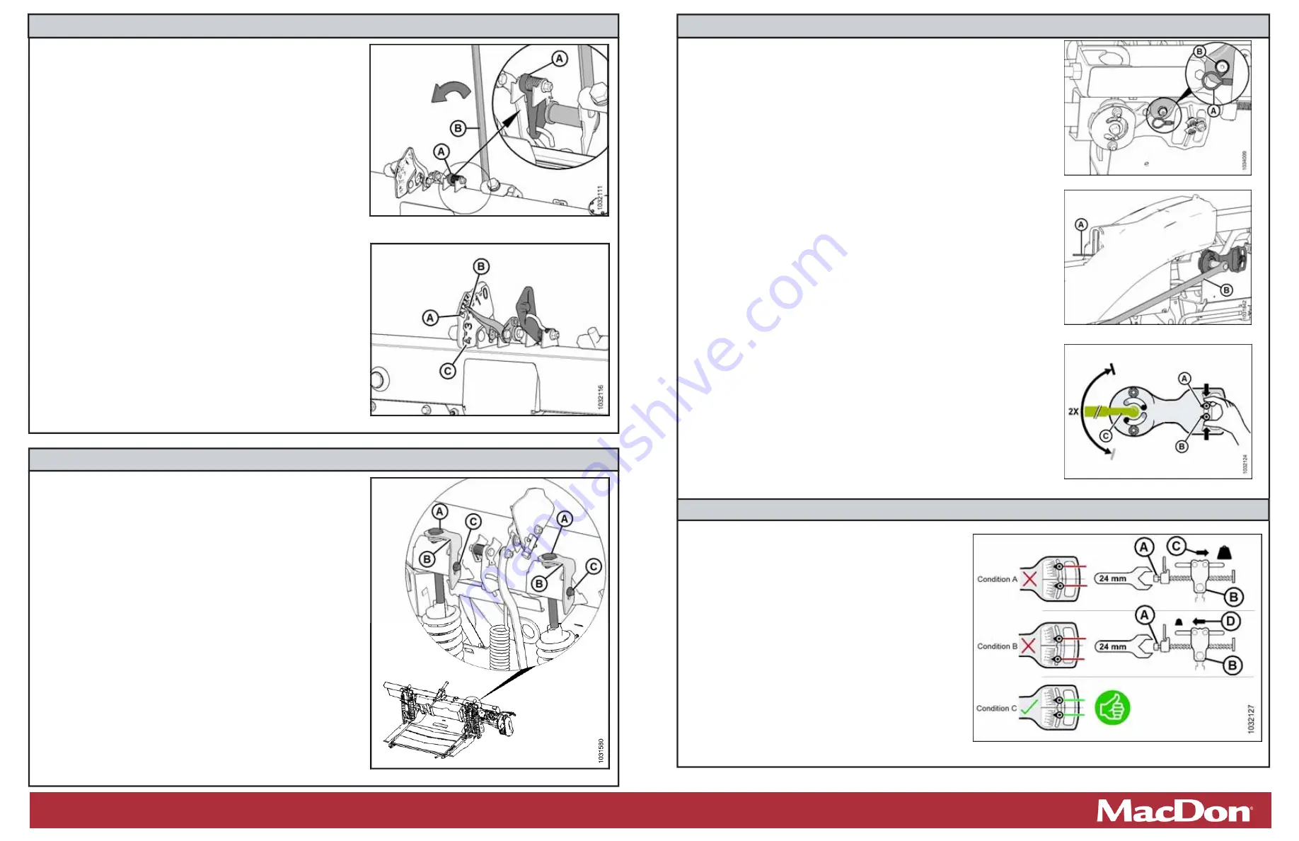
g. Refer to Figure 10 and compare the two readings as follows:
•
Condi on A
–
the wing is too light; make wing heavier.
•
Condi on B
–
the wing is too heavy; make wing lighter.
•
Condi on C
–
wing balance correctly adjusted. Reinstall the linkage cover, and
repeat the procedure on the opposite wing.
Step 4: Checking Wing Balance
a. If the wing is too light (Condi on A), make it heavier by
turning adjuster bolt (A) to move clevis (B) in direc on (C).
b. If the wing is too heavy (Condi on B), make it lighter by
turning adjuster bolt (A) to move clevis (B) in direc on (D).
c. Recheck wing balance. Adjust as required un l wing is
balanced (Condi on C).
d. Move the spring handle to the upper (LOCK) posi on.
e. If the lock does not engage, move the wing up and down
with tool un l it locks.
f. Detach
the
fl
ex checker cable from the
fl
ex checker lock.
g. Repeat on the other side.
h. Return the tool to its storage loca on, and reinstall the
linkage cover.
Step 5: Adjus
Ɵ
ng Wing Balance
Figure 8: Wing Balance Linkage
Figure 9: Wing Balance Adjustment
Figure 6: Float Adjustment Bolts – Le
Ō
Side Shown
The Harvesting Specialists. MacDon.com
Figure 10: Wing Balance Adjustment
Figure 7: Flex Checker Cable


