


9
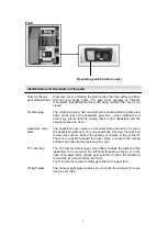
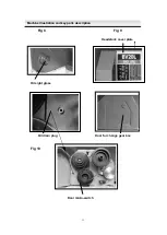
Fig 5
Reversing switch (under cover)
Door for change
gear compartment
Protective cover, enclosing the motor pulley, the drive pulley and drive
belt and the change gears. The gear cover operates an interlock
microswitch that will prevent the motor being started if the cover is not
closed.
Oil drain plug
The oil drain plug is a hex head bolt with a sealing washer located low
down at the rear of the headstock gear box, - when refitting the oil
drain plug ensure that the mating faces of the headstock and the
sealing washer are clean.
Headstock cover
plate
The headstock cover plate is a flat metal plate secured to the top of
the headstock gearbox by four cap head bolts. Unscrew the bolts and
remove the cover to inspect the gearbox or replace or top up the oil.
There is no gasket beneath the cover plate, so ensure the mating
surfaces are clean before replacing the cover.
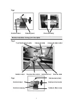
18T reversing
The 18T reverse tumbler gear, when fitted, enables the rotation of the
leadscrew to be reversed, For left hand threads (as Fig 6) or in the
case of an asymmetric change gear selection to allow the leadscrew
to maintain its correct rotation (as Fig 7).
Fig 11 shows the reverse tumbler gear fitted in the gear train.
Oil sight glass
The oil level sight glass enables you to check the amount of oil you
have in your lathe.
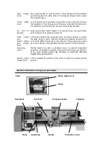
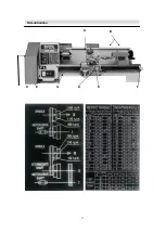
Identification and Description of the parts
Identification and Description of the parts of the BV20-BL Lathe
Содержание BL200L
Страница 1: ...N Index of Contents BENCH LATHE BL200L BV20L OPERATION MANUAL ...
Страница 10: ...10 ...
Страница 13: ...13 D H E G A C F Oil Lubrication Identification and Description of the parts of the BV20 BL Lathe B ...
Страница 14: ...14 ...


