


61
3. In AUTO mode
The unit operates in corresponding sleep mode adapted to the
automatically selected operation mode.
4. In FAN mode
The SLEEP function will not be available under the FAN mode.
5. When quiet sleeping function is set to 8 hours the quiet sleeping
time can not be adjusted. When TIMER function is set, the quiet
sleeping function can't be set up. After the sleeping function is
set up, if user resets TIMER function, the sleeping function will be
cancelled; the machine will be in the state of timing-on, if the two
modes are set up at the same time, either of their operation time
is ended first, the unit will stop automatically, and the other
mode will be cancelled.
Note:
• When TIMER function is set, the sleeping function can't be set up.
After the sleeping function is set up, if user resets TIMER function,
the sleeping function will be cancelled; the machine will be in the
state of timing-on.
• Power failure resume: Press the sleep pad ten times within five sec-
onds and enter function after hearing four sounds. And press the
sleep pad ten times within five seconds and leave this function af-
ter hearing two sounds.
• Power failure resume function: If the unit is started for the first
time, the compressor will not start running unless 3 minutes have
elapsed. When the power resumes after power failure, the unit
will run automatically, and 3 minutes later the compressor starts
running.
healthy airflow
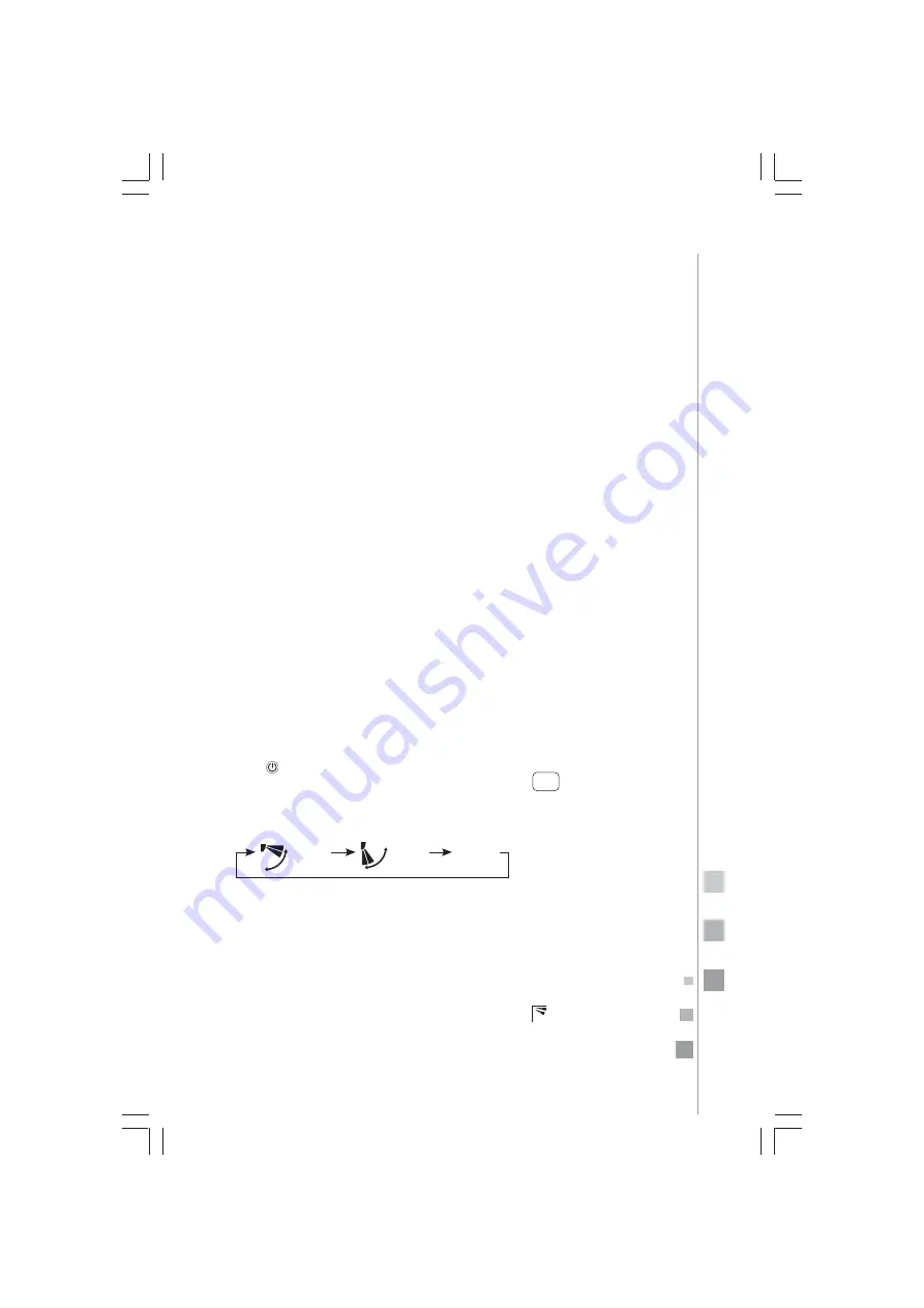
1. Press to start.
2. Repeatedly press the HEALTH AIRFLOW button . The louver
position will cycle between the following three settings. Select
the position you require.
Notes:
• Do not adjust the position of the louver manually. Otherwise, the
louver will not operate correctly. If the louver does not run cor-
rectly, stop it for a minute and then restart using the remote con-
trol.
• After setting the healthy airflow function, the position of the lou-
ver will be fixed.
• During COOLING, it is better to select this mode
• Under COOLING and DRY modes, using the air conditioner for a
long time when air humidity is high can result in condensed water
on the louver.
HEALTH
AIRFLOW
Healthy
Airflow
UP
Healthy
Airflow
DOWN
CANCEL
Содержание MMT12CABSCAM8
Страница 2: ...2...
Страница 18: ...hasta llegar a 24 horas...
Страница 38: ......
Страница 62: ...62 until reaching 24 hours...
Страница 82: ......
Страница 91: ...91 notas notes...
Страница 92: ...92 notas notes...
Страница 99: ...99...
Страница 100: ...100...