


MAAG-14000-E-02EMEA
7
S SERIES TWIN SCREW PUMPS
S E C T I O N 4
O P E R AT I O N
PUMP PREPARATIONS
The final pre-startup check is very important to avoid operational
difficulties . Listed below are several key components to be checked
prior to pump operation:
STEP 1
Inspect all piping . Check individual piping support; check for leaks
and unnecessary piping strain on the pump; flush all piping to
ensure removal of foreign material from the system; check that
all valves and gauges are functional; check mesh-size suitability .
STEP 2
Ensure pump cavity is filled with pump fluid .
STEP 3
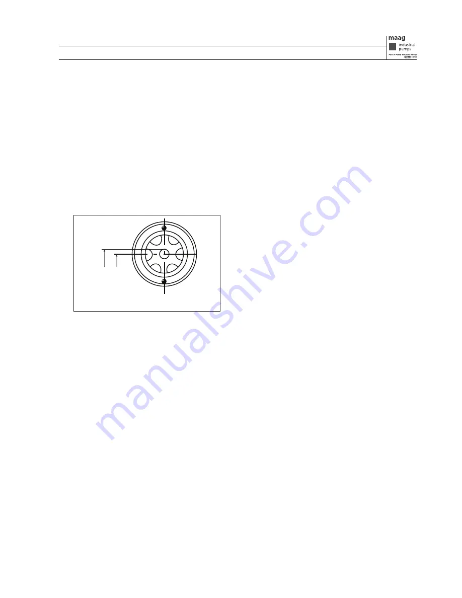
Check that oil is at the proper level in the gear housing . Excessive
oil will cause the gear box to overheat (see Figure 6) .
STEP 4
Check pressure gauges and all other meters .
STEP 5
Check all electrical equipment (i .e ., cables, control lines and
accessories) .
If pump is jacketed for heating, heat the pump casing to the
prescribed temperature . Steam, hot water and hot oil can
be used as a heating medium . According to the different
materials of the pump casing, select proper pressure for
heating medium within the limit of 2 .0 to 8 .0 bar (29 .0 to
116 psi) . Inlet and outlet are located on the pump casing;
therefore, the thermal difference between pumped fluid
and heating medium should be as small as possible in order
to avoid generating internal stress . Especially for cast-iron
pumps, the thermal difference between the pumped fluid
and the heating medium should be less than 50°C (122ºF) .
If the pump is installed with a double mechanical seal, then
sealing the liquid system is required . The pressure for sealing the
liquid system should be 1 .0 to 2 .0 bar (14 .5 to 29 .0 psi) higher
than that of the pump suction chamber . All rules and regulations
regarding sealing the liquid system should be adhered to as
described in the Sealing Liquid System Instructions .
STEP 6
Check rotation shafts by rotating the coupling by hand to
determine whether the pump shafts and motor shaft turn
freely . If any rubbing or binding occurs, the cause must be
located and corrected before starting the pump .
STEP 7
Check that motor rotation is correct; refer to the rotation
directional mark located on the pump .
STARTING THE PUMP
STEP 1
Open the suction and discharge valves wide in order to keep
the entire piping system unobscured .
NOTE: Ensure that all valves and devices on the suction and
discharge sides are opened before starting the pump .
STEP 2A
If pump is installed with a heating jacket, introduce heating
medium and heat the pump to the temperature as described
in previous section .
STEP 2B
If pump is equipped with double mechanical seals, introduce
sealing liquid and monitor the sealing liquid system .
STEP 3
Rotate the coupling by hand to determine if rubbing or
binding occurs .
STEP 4
Start motor/driver .
STEP 5
The pump must be stopped if there is no capacity after
starting . Restart the pump after several minutes . If there is still
no capacity, the cause must be determined . Please refer to the
Troubleshooting section of this manual for further instruction .
RUNNING THE PUMP
STEP 1
Check the pumping unit for unusual noise or vibration . Any
unusual vibration or change in sound must be investigated
and corrected to normal operating conditions .
STEP 2
Check bearing housing temperature . Bearing temperature
can safely rise to between 65°C and 75°C (149ºF and 167ºF) .
Pumped medium or spot environmental temperature should
be considered when determining whether temperature
exceeds normal operating conditions .
Bearing temperature up to 90°C (194ºF) is considered to be normal .
Within this limit, the stability of the temperature is the best indicator of
normal operation . A sudden increase in temperature indicates that a
bearing problem is developing and the bearing should be checked
immediately .
CAUTION: Do not attempt to measure the temperature by hand!
STOPPING THE PUMP
STEP 1
Stop the motor and pump .
STEP 2
Close suction and discharge valves .
STEP 3
If pump is installed with a heating device, stop the heating
device first, then close the sealing system after cooling .
FIGURE 6 Oil Level of the Gear Casing
max
min
Содержание S Series
Страница 12: ...S E C T I O N X NOTES...
Страница 13: ...S E C T I O N X NOTES...
Страница 14: ...S E C T I O N X NOTES...