

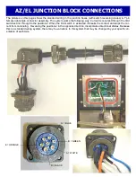

FINAL SETUP OF THE LIMIT SET SCREWS:
We have included (2) limit screws, one for each limit switch. The limit screws can be setup at any position based
upon the orientation of your choice. On Azimuth and Elevation use the supplied 8
-
32 x
1/2”
set screws and 5/64
allen wrench.
DO NOT INSTALL AT THIS TIME
. You can always make slight adjustments to the limit screw if
necessary. We have provided adjustment holes at every 5°. We suggest leaving the cover off of the unit until you
have completed your testing.
LSK
-
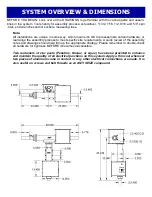
1000 OVERVIEW:
The
LSK
-
1000
limit switch kit is a physical hard backup limit. The standard control unit supplied with our AZ or EL
has
“
Electronic Limits
”,
but the
LSK
-
1000
limit switch kit, has been designed as a physical backup system in
the event of a control unit failure. The factory has pre
-
installed the
LSK
-
1000
limit switch kit into the AZ and EL
units for you. Typically the
LSK
-
1000
limit switches only need to be setup once, but can be adjusted when neces-
sary.
LSK
-
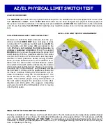
1000 MANUAL LIMIT SWITCH PRE
-
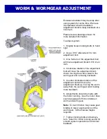
TEST:
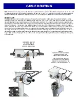
Remove one half of the black enclosure from the po-
sitioner unit that
DOES NOT
have cord grips or wires
running into it. You will see the limit switches
(A,B)
the
limit arm
(C),
and limit screw
(D)
as pictured to the
right.
We have not installed the limit screw due to
unknown customer orientation
. Move the supplied
RC2800
control unit near the positioner for proper limit
switch testing. With the positioner wired to the control
unit, turn the control unit on. Be sure to test the proper
direction of each positioner before moving forward.
Once you have determined the correct direction of ro-
tation from the control units
’ “
Control Buttons,
”
deter-
mine which limit switch will be activated by the rotation
of the main gear and limit screw. Press a known direc-
tion using the
“
Control Buttons,
”
and manually activate
the limit switch. At this point the positioner should stop
it
’
s travel. Continue holding the limit switch and re-
verse the direction using the
“
Control Buttons.
”
The
motor should move away from the engaged limit
switch. This confirms proper wiring and operation of
the limit switch. Repeat this procedure for the other
direction and limit switch. We suggest, completing
each axis (ie Azimuth and Elevation) prior to moving
onto the final setup.
C
A
B
D
AZ/ EL
-
1000 LIMIT SWITCH ARANGEMENT
AZ/EL PHYSICAL LIMIT SWITCH TEST


